
Oster BLSTSS-PZO Circuitboard Replacement
crwdns2944107:0crwdnd2944107:0Tristian Cruzcrwdnd2944107:0crwdnd2944107:0crwdnd2944107:02crwdnd2944107:0crwdne2944107:0
crwdns2944111:0January 14, 2018crwdne2944111:0
crwdns2915892:0crwdne2915892:0
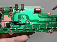
crwdns2942287:0crwdne2942287:0The circuit board is the main control center of the blender.
crwdns2942213:0crwdne2942213:0
crwdns2943215:0crwdne2943215:0


crwdns2944105:0crwdne2944105:0
-
-
Use the prying tools to open the four plastic screw holes on the bottom of the blender.
-
-
-
Use the Phillips #1 Screwdriver to unscrew the four 16 mm screws and remove the plastic bottom.
-
-
-
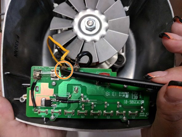
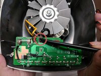
Use the spudger to detach the black wire from the circuit board.
-
Repeat for yellow wire.
-
-
-
Use the Phillips #1 to remove the four 8mm screws.
-
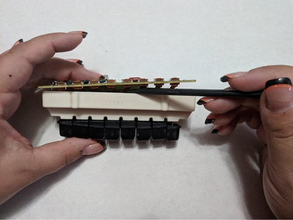
Use the medal spudger to detach the circuit board from the buttons.
-
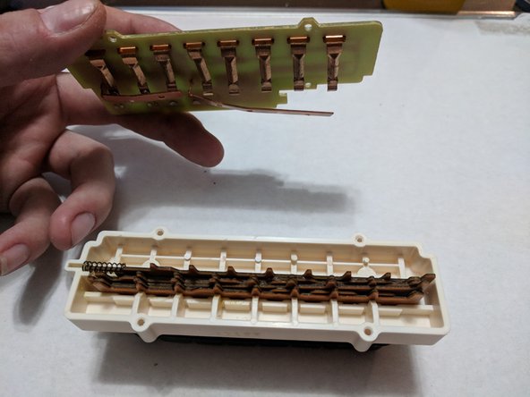
Gently pull and release circuit board from buttons.
-


To reassemble your device, follow these instructions in reverse order.
To reassemble your device, follow these instructions in reverse order.
crwdns2935221:0crwdne2935221:0
crwdns2935227:0crwdne2935227:0
crwdns2915084:0crwdne2915084:0

University of North Texas, Team S7-G8, Thomas Fall 2017 crwdns2935289:0University of North Texas, Team S7-G8, Thomas Fall 2017crwdne2935289:0
UNT-THOMAS-F17S7G8
crwdns2931471:03crwdne2931471:0
crwdns2935297:04crwdne2935297:0
crwdns2947412:02crwdne2947412:0
Where can I get a replacement part for this PCB assembly? My buttons stick and don’t work properly.
It’s the button pushing assembly that’s defective.
Where can I get a replacement part for this PCB assembly? My buttons stick and don’t work properly.
It’s the button pushing assembly that’s defective.