crwdns2915892:0crwdne2915892:0
Follow this guide to replace a faulty motherboard in the Nintendo Switch game console.
The Switch uses JIS screws, but you can use a Phillips screwdriver in a pinch. Be very careful not to strip the screws. iFixit's Phillips bits are designed to be cross-compatible with JIS-style screws.
Note: When you remove the shield plate, you’ll need to replace the thermal compound between the plate and the heatsink. Since normal thermal paste isn’t designed to bridge large gaps, the closest replacement is K5 Pro viscous thermal paste. You will, however, need regular replacement thermal paste for the CPU.
Note: There are two different models for the Nintendo Switch (model HAC-001, released in 2017, and model HAC-001(-01), released in 2019). Make sure your replacement motherboard is compatible with your specific Switch console.
crwdns2942213:0crwdne2942213:0
-
-
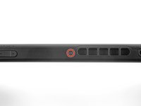
Press and hold down the small round button on the back of the Joy Con controller.
-
While you hold down the button, slide the controller upward.
-
-
-
Continue sliding the Joy Con upward until it's completely removed from the console.
-
-
crwdns2935267:0crwdne2935267:0Magnetic Project Mat$19.95
-
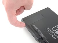
Use a Y00 screwdriver to remove the four 6.3 mm-long screws securing the rear panel.
You're screwed
I found a better method of removing the battery:
1. Get isopropyl in the battery groove.
2. Use the spudger to lift a corner slightly.
3. Use dental floss to under the corner and carefully floss under the battery. This will remove the adhesive in a very clean and easy way because you allow the isopropyl to get further down!
Ich fand auch meine eigenen viel einfacher. Wenn Sie Tausende von Spielen verschiedener Anbieter in einer sicheren Umgebung spielen möchten, ist Spinia das ideale Online-Casino für Sie. Wenn Sie Hilfe bei der Nutzung der Spiele, der Inanspruchnahme von Boni, der Teilnahme an Werbeaktionen oder Einzahlungen benötigen, nutzen Sie die Live-Chat-Option oder senden Sie dem Online-Casino eine E-Mail. Besuchen Sie https://casinosanalyzer.de/casino-bonus/... für weitere Details. Um Ihre Casinoausgaben zu kontrollieren, können Sie persönliche Einzahlungsobergrenzen festlegen. Wohltätigkeitsorganisationen wie Gamblers Anonymous, Gambling Therapy und GamCare sind Anlaufstellen, an die Sie sich wenden können, wenn Sie glauben, dass Sie ein Spielproblem haben.
this $@$* is difficult asfk please dont do this
-
-
-
Use a JIS 000 driver or an official iFixit PH 000 driver to remove the following screws securing the rear panel:
-
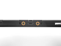
One 2.5 mm-long screw on the top edge of the device
-
Two 2.5 mm-long screws on the bottom edge of the device
My screw doesn’t seem to be a JIS 000, the same screwdriver I used for the step before doesn’t work for this one.
What worked for me was a Phillips 000
-
-
-
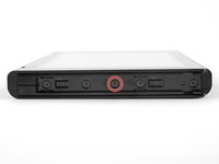
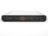
Use a JIS 000 screwdriver or an official iFixit PH 000 driver to remove the two 3.8 mm center screws on the sides of the device (one on each side).
-
-
-
Use your finger to flip up the kickstand on the back of the device.
-
-
-
Use a JIS 000 screwdriver or an official iFixit PH 000 driver to remove the 1.6 mm screw in the kickstand well.
-
Close the kickstand.
-
-
-
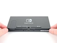
Open the game card cartridge flap.
-
Lift the rear panel up from the bottom of the device and remove it.
How to remove micro SD port?
Entre el paso 7 y paso 8 falta indicar que hay que retirar los dos tornillos a cada lado de la entrada usb
-
-
-
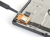
Use a JIS 000 screwdriver or an official iFixit PH 000 driver to remove the 3.1 mm screw securing the microSD card reader to the device.
-
-
crwdns2935267:0crwdne2935267:0Tweezers$4.99
-
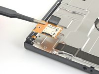
Use your fingers or a pair of tweezers to lift the microSD card reader straight up from the device to disconnect and remove it.
I cant get the card reader to stay connected to the motherboard when trying to reassemble it. Help needed.
Directions were great and very helpful! Saved time and money doing myself.
I found that tightening the screw for the sd reader all the way down caused the original sd reader to not seat correctly.
I finished the repair and its not recognizing anything. Ive downloaded a couple more games to the hard drive while I was procrastinating the repair, could a desyncronization issue be causing this?
I have the new reader plugged in but my nintendo switch wont turn on now.
try to hold thepower button for a bit it might just be shut down hold the buutton for at least 30 seconds or just wait for it to turn on
I have same issue. Console is dead
Kenny -
The Y screws are horrible. The bit in the took kit only managed to get two of them out. I have a Y0 bit that got the other two out. What a stupid design those are. Kit should include replacement screws and maybe a new foam pad for the SD Card Reader. New SD card module is tricky to get the connection.
Foam pad no longer sticky enough to hold down the connector. Is there any place to get a replacement sticky pad or a work around to keep the connection secure?
My name is hello djdjdjdnd
-
-
-
Use a JIS 000 screwdriver or an official iFixit PH 000 driver to remove the six 3 mm screws securing the shield plate to the device.
Between Step 6 and Step 7, there is a missing step of disconnecting and removing the SD Card reader.
@theomat Step 7 and 8 show the removal of the SD Card reader.
Step 7 and 8 do not show that. It is completely missing. You show the card reader as being absent, but now how it came to BE absent. A lot of people will try to pull the shield out, presuming the reader is meant to come out with it. Why not update the guide?
Are you seeing something different then what’s seen in this screenshot? https://jmp.sh/PdfdhSy
@blakeklein I am not seeing that part of the tutorial, no.
Now I need to find the screw type of this sd card reader ^^
Maybe my last 3.1mm philips #000 screw? (reassembling phase)
Agreed, still missing that step… I don’t have the image that is in your linked screenshot.. but your screenshot doesn’t mention removing a 7th screw anyway. I had my screwdriver underneath trying to pry it open before realizing there was another screw holding it all together.
Sorry everyone! The guide was missing a prerequisite guide. The missing SD card steps should be there now.
I’m afraid the steps are still missing :-( But the comments helped.
-
-
crwdns2935267:0crwdne2935267:0Tweezers$4.99
-
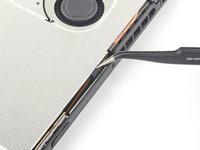
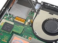
Use your fingers or a pair of tweezers to peel back the piece of foam on the top edge of the device near the fan exhaust port.
-
-
-
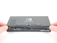
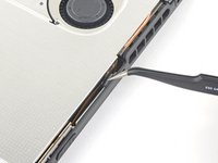
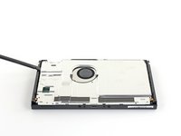
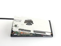
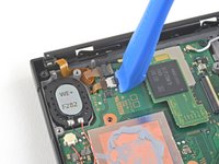
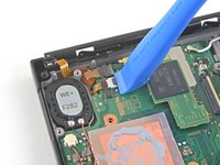
Insert a spudger underneath the shield plate along the edge of the device.
-
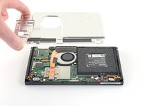
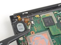
Pry up to lift the shield plate and remove it from the device.
-
You can reuse the pink thermal compound if you're careful. Keep the compound clean and make sure it makes solid contact between the heat sink and the shield during reassembly.
-
If you need to replace it, refer to our thermal paste guide to remove the old thermal compound and replace it with an appropriate compound, such as K5 Pro, during reassembly.
I’d recommend replacing the thermal compound to ensure that the cooling system works as intended.
I really don’t understand in what areas I should be replacing the thermal paste.
Do I leave the giant pink glob that’s present on the back plate or replace that as well?
Or do I only apply it under the heat sink and on the motherboard?
-
-
-
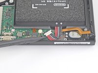
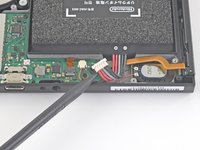
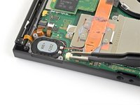
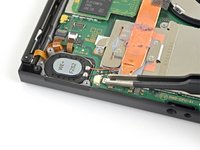
Use the point of a spudger to pry the battery connector straight up and out of its socket on the motherboard.
My battery connector won’t go back on :( dunno what to do.
It is possible to just slide the old rail out after this step, and slide in the new one.
-
-
-
-
Use a JIS 000 screwdriver or an official iFixit PH 000 driver to remove the three 3 mm screws securing the heat sink to the motherboard.
You do know that you can just do it without removing the motherboard
If you are reading this, John said hello
-
-
-
Carefully peel the two foam pieces stuck over both the heatsink and the fan away from the fan.
-
Insert the point of a spudger underneath the part of the foam that isn't stuck against anything,
-
Press the top of the foam with your finger to hold it in place.
-
Roll the spudger tip underneath the foam all the way to the other end of the foam to release it.
Where could I get replacement foam tape?
I am not 100% sure, but based on the fact that the purpose of this foam is to conduct heat, I believe it's "glued" with thermal paste.
Alex -
-
-
-
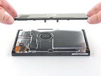
Use a spudger or your fingers to lift the heatsink up and off the motherboard to remove it.
-
Apply thermal paste to all surfaces that had thermal paste applied previously. This includes between the heatpipe and aluminum shield, which the Switch uses as additional heatsinking.
Thermal paste
Exactly how much thermal paste should be applied to the CPU and which application method should be used? The linked instructions list four methods (vertical line, horizontal line, middle dot, or surface spread) but it’s not clear to me which one is appropriate for the Switch. Thanks.
-
-
-
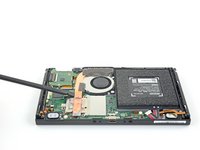
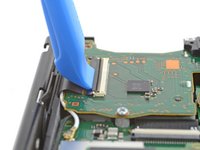
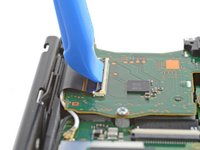
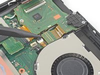
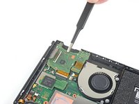
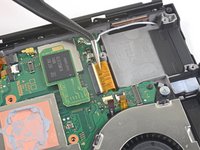
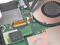
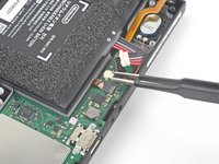
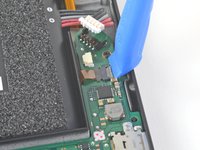
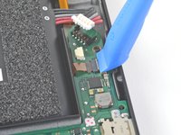
Use an opening tool or your fingernail to flip up the small, hinged locking flap on the digitizer cable's ZIF connector.
12345$:@/!:&;&; and
Update: If your Switch has lost the ability to read games and or the headphone jack in addition to touchscreen functionality, please consider reading this thread and its solution: Nintendo Switch Cartridge Reader Not Working After Fan Replacement
-
-
crwdns2935267:0crwdne2935267:0Tweezers$4.99
-
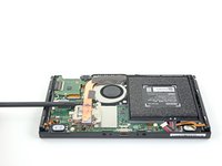
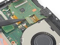
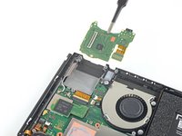
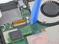
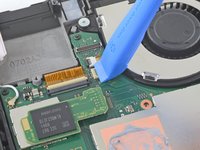
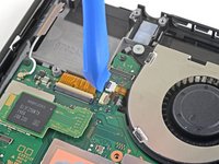
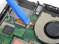
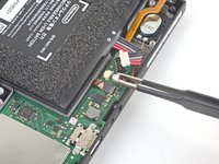
Use a pair of tweezers to slide the digitizer cable horizontally out of its connector on the game card reader board.
It was not clear form the picture, but you need to pull sideways out toward the edge of the Switch where the JoyCon attaches, not up away from the motherboard.
Thanks for the feedback! I’ll adjust the wording to reflect this.
ribbon cable slides towards joycon side...not straight up. revise text please..."horizontally" still not totally clear for novice (like myself)
DONT DO THIS!! Just leave this long ribbon and fold it like a book. DO NOT DETACH IT. My touchscreen and gamecard reader are broken now because in the reverse i never managed to fix it properly i have done it like 20x times, headphone jack works. I cant play physical copies anymore on this switch and no touchscreen. Thanks for nothing ><!
maybe don't follow this advice, i did this and my digitizer cable snapped right off. don't know if mine was just broken from the start but i'd still advise against this
qu in n -
DO NOT DO THIS STEP. Disconnecting the cable from the connector has been known to irreversibly damage this piece, disabling your Switch's ability to read game cartridges, touchscreen, and headphone jack. This is a known issue that has not been addressed in any guide with this step, with the issues being documented as far back as 2019.
To anyone who has done the reverse of this step successfully, especially original author Craig Lloyd, please explain how one can reconnect the digitizer cable to the board and return functionality to the touchscreen and cartridge reader. If you know how, please respond to this comment and amend this step with either photos or a video of how to properly reconnect it. Otherwise, any guide with this step will do and will continue to do damage to Switches.I just did it without an issue. I used a pry tool to take it off, but just use my fingers to re install it. I lined up the ribbon and wiggled it a tiny bit and it popped right in. I just tested my fix and everything works as before. Except now the fan works. I do hate these style connectors though, on a laptop I have one durn to dust as I tried to take it out.
@cottertechnogy When you describe the ribbon popping back in, what was the feeling of it? It literally felt like it clicked in, like it attached to something inside the connector? Did it make a sound once it popped in?
Yes, it was like it set where it was supposed to. When I flipped down the retaining clip I was just hoping. A magnifying lense would have been helpful, I misplaced mine. I read this disclaimer after I already took it off...so if I do this again I'll leave it connected. Maybe the clip isn't totally seated? Sounds like you have been through the ringer.
@cottertechnogy Your input is appreciated. I attempted to reconnect my own Switch's ribbon to the connector after reading this, trying to see if I've missed the "clicking" feeling of successfully re-seating it. It looks properly re-seated and as far as I can tell the ribbon does not go further into the connector, but I didn't not feel it popped in, per se. I believe this tip can still help others doing these repairs, but unless I am missing something, this still does not do it for me. Thank you again.
Update: The iFixIt community has discovered a solution to this problem. Please give this thread and it's solution a read: Nintendo Switch Cartridge Reader Not Working After Fan Replacement
If this solution does not work for you, please comment below.@cottertechnogy When you describe the ribbon popping back in, what was the feeling of it? It literally felt like it clicked in, like it attached to something inside the connector? Did it make a sound once it popped in?
-
-
-
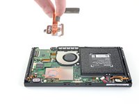
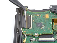
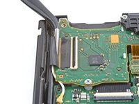
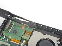
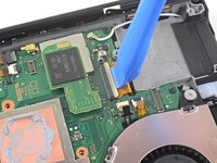
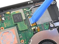
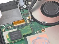
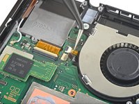
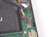
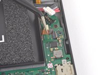
Use the point of a spudger to pry the headphone jack and game card reader connector straight up to disconnect it from the motherboard.
-
-
-
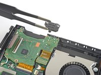
Use a JIS 000 screwdriver or an official iFixit PH 000 driver to remove the three 3.1 mm screws securing the headphone jack and game card reader board to the device.
-
-
-
Use a pair of tweezers or your fingers to remove the headphone jack bracket.
-
-
-
Use a pair of tweezers or your fingers to remove the headphone jack and game card reader board.
-
-
-
Use an opening tool, spudger, or your fingernail to flip up the small, hinged locking flap on the LCD ribbon cable ZIF connector.
I hoped to see this before... I think i scratch mine to hard... only backlight works and it doesnt turn on
Afonso -
-
-
crwdns2935267:0crwdne2935267:0Tweezers$4.99
-
Use a pair of tweezers to pull the ribbon cable straight out of its connector on the motherboard.
-
-
-
Use an opening tool, spudger, or your fingernail to flip up the small, hinged locking flap on the fan cable ZIF connector.
-
-
-
Use a pair of tweezers to pull the fan cable straight out of its connector on the motherboard.
-
-
-
Use an opening tool, spudger, or your fingernail to flip up the small, hinged locking flap on the power and volume button ribbon cable ZIF connector.
-
-
-
Use a pair of tweezers to pull the ribbon cable straight out of its connector on the motherboard.
-
-
-
Use an opening tool, spudger, or your fingernail to flip up the small, hinged locking flap on the smaller LCD ribbon cable ZIF connector.
-
-
-
Use a pair of tweezers to pull the ribbon cable straight out of its connector on the motherboard.
-
-
-
Use the point of a spudger, an opening tool, or your fingernail to flip up the small, hinged locking flap on the Joy Con sensor rail's data cable ZIF connector.
-
-
-
Use a pair of tweezers to pull the ribbon cable straight out of its connector on the motherboard.
-
-
-
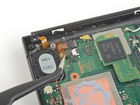
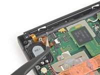
Use the point of a spudger to pry up the black antenna cable straight up out of its socket on the motherboard.
-
-
-
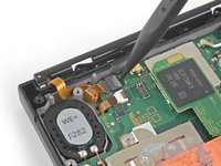
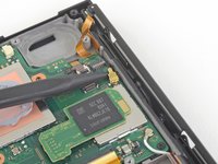
Use the point of a spudger to pry up the white antenna cable straight up out of its socket on the motherboard.
-
-
-
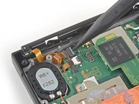
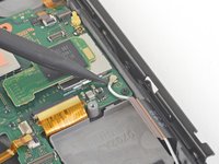
Use your fingers or a pair of tweezers to pull the right speaker connector straight out of its socket on the motherboard.
-
-
-
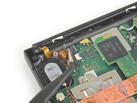
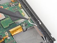
Use your fingers or a pair of tweezers to pull the left speaker connector straight out of its socket on the motherboard.
-
-
-
Use an opening tool, spudger, or your fingernail to flip up the small, hinged locking flap on the Joy Con sensor rail data cable ZIF connector.
-
-
-
Use a pair of tweezers to slide the Joy Con rail data cable straight out of its connector on the motherboard.
-
-
-
Use a JIS 000 screwdriver or an official iFixit PH 000 driver to remove the following screws:
-
Four 2.5 mm screws
-
Two 3.1 mm screws
-
-
-
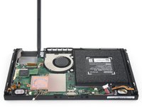
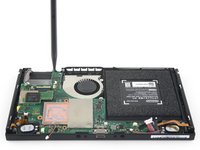
Insert a spudger into a gap between the motherboard and the frame.
-
Carefully lift up the motherboard and remove it from the frame.
-


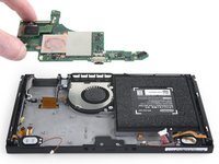
Compare your new replacement part to the original part. You may need to transfer remaining components or remove adhesive backings from the new part before installing.
To reassemble your device, follow these instructions in reverse order.
Take your e-waste to an R2 or e-Stewards certified recycler.
Repair didn’t go as planned? Try some basic troubleshooting, or ask our Nintendo Switch Answers community for help.
crwdns2935221:0crwdne2935221:0
crwdns2935229:0103crwdne2935229:0

crwdns2947412:05crwdne2947412:0
Thanks for the guide, Blake. Just one thing: this guide skips over the removal of the MicroSD card holder and flex cable. This piece should be removed between steps 6 and 7.
порадовала норма 1-2 часа))))) у нас на производстве нинтендо норма в среднем 4 минуты на полный разбор
The step to remove SD card board is missing.
J'ai un problème avec la puce +max 77621aewi p de ma switch de 2017 comment faire pour la réparer
Would love to know the answer to this as well.
Ich fand auch meine eigenen viel einfacher. Wenn Sie Tausende von Spielen verschiedener Anbieter in einer sicheren Umgebung spielen möchten, ist Spinia das ideale Online-Casino für Sie. Wenn Sie Hilfe bei der Nutzung der Spiele, der Inanspruchnahme von Boni, der Teilnahme an Werbeaktionen oder Einzahlungen benötigen, nutzen Sie die Live-Chat-Option oder senden Sie dem Online-Casino eine E-Mail. Besuchen Sie https://casinosanalyzer.de/casino-bonus/... für weitere Details. Um Ihre Casinoausgaben zu kontrollieren, können Sie persönliche Einzahlungsobergrenzen festlegen. Wohltätigkeitsorganisationen wie Gamblers Anonymous, Gambling Therapy und GamCare sind Anlaufstellen, an die Sie sich wenden können, wenn Sie glauben, dass Sie ein Spielproblem haben.
marryjonathan259 - crwdns2934203:0crwdne2934203:0
nice post of yours
marryjonathan259 - crwdns2934203:0crwdne2934203:0