crwdns2915892:0crwdne2915892:0
Follow this guide to replace the right joystick in your Nintendo Switch Lite. Replacing the joystick will fix the notorious “Joy-Con drift” issue. (Follow this guide to replace the left joystick in your Nintendo Switch Lite).
The Switch Lite uses JIS screws, but you can use a Phillips screwdriver in a pinch. Be very careful not to strip the screws. iFixit's Phillips bits are designed to be cross-compatible with JIS-style screws.
After the repair, recommend to calibrate the replaced joystick before playing any games.
Note: This procedure requires removing the shield plate and heat sink. The thermal paste will need to be cleaned off of both components—as well as the CPU—and reapplied before reinstalling the shield plate and heat sink.
crwdns2942213:0crwdne2942213:0
-
crwdns2935267:0crwdne2935267:0Magnetic Project Mat$19.95
-
Use a Y00 screwdriver to remove the four 6.3 mm-long screws securing the back panel.
-
-
-
Use a JIS 000 driver or an official iFixit PH 000 driver to remove the following screws securing the back panel:
-
Two 3.6 mm-long screws on the top of the device
-
Two 3.6 mm-long screws on the bottom of the device
I accidentally stripped the back screw and now I can't open it. I removed all the other screws. What should I do?
-
-
-
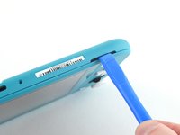
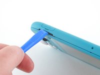
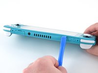
Insert an opening tool into the left speaker grille on the bottom of the device.
-
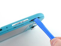
Twist the opening tool to release the clips securing the back panel.
-
-
-
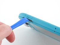
Slide the opening tool around the bottom-left corner to release the clips on the left side of the device.
-
-
-
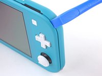
Insert an opening tool into the right speaker grille on the bottom of the device.
-
Twist the opening tool to release the clips.
-
-
-
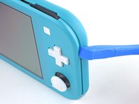
Slide and pry the opening tool around the bottom-right corner to release the clips on the right side of the device.
-
-
-
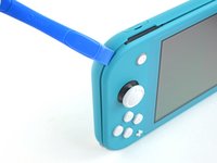
Continue sliding and prying the opening tool along the gap on the top of the device to release the clips.
The headphone jack prevents you from completely freeing or lifting the back panel straight up. Unclip your way around the back cover, then lift from the side with the US port and slide it off the heaphone jack.
-
-
-
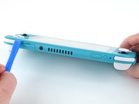
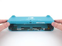
Lift the bottom edge of the back panel, opening it like a book.
-
Remove the back panel.
-
-
-
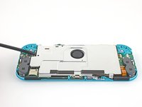
Use a JIS 000 driver or an official iFixit PH 000 driver to remove the following four screws:
-
Three 3.1 mm screws
-
One 4.5 mm screw
There are four screws instead of three mentioned
it doesnt mention 3 anywhere, and it labels all four
With how easy it seems to be to do serious damage with the next few steps, I figured I'd say that realistically you can skip steps 9-13 when doing this repair. While they provide a bit of extra security by disconnecting the battery, the left stick is completely accessible and replaceable without touching the heat shield or anything underneath (And steps 17 and 18 disconnect power from the daughter board regardless).
i stripped a &&^&^$^ screw
Well I actually removed the screw right next to the 4.5 screw. I did not realize it till my son showed me why the plate wouldn't release. Ha ha, it's funny now but yeah not a big deal. I could have bent it badly assuming I took all screws out though. For anyone reading this before going in. 👍
the one in the middle rounded out .-.
-
-
-
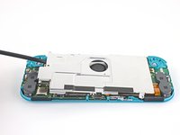
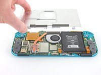
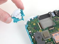
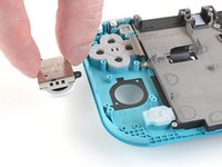
Use a spudger or your fingers to lift the shield plate up and out of the device.
-
Remove the shield plate.
You may need to replace the thermal paste on the heat sink.
What type of Thermal Paste would you guys recommend? I clicked on the picture but nothing.
Personnaly i use some Mx-6 from Artic, really good quality/price, never have to complain.
Nothing -
-
-
-
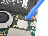
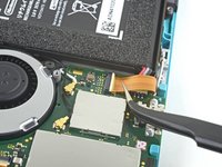
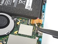
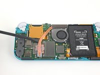
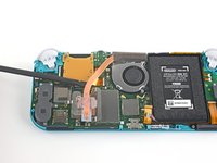
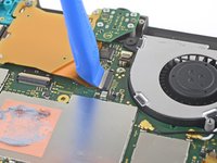
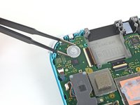
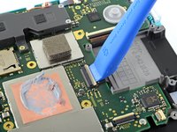
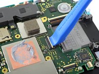
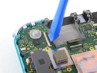
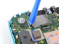
Use an opening tool or your fingernail to flip up the small, hinged locking flap on the motherboard interconnect cable's ZIF connector.
The clip broke off when trying to remove this cable. Audio only works through headphones and the display now won’t turn on after the clip broke. Does anyone know where I could get a clip or how I could fix it without it?
Mi è successa la stessa cosa è non so come ripararla! Chissà se c’è un modo!
-
-
-
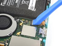
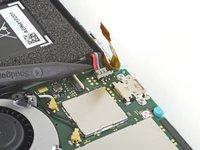
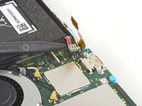
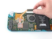
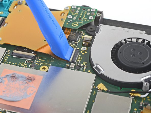
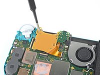
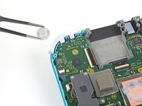
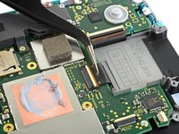
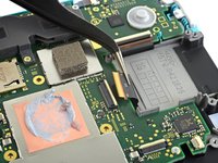
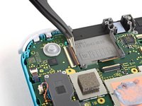
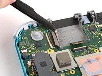
Use a pair of tweezers to slide the interconnect cable out of its connector on the motherboard.
I turned the unit off beforehand, I used tweezers just like the instructions said (ifixit branded) , my device sparked and now it won’t turn back on
The flap came off is it important or is there a way t fix it?
We're you able to get it working without the white flap? My screen is not working after putting it back together and i noticed this white flap was falling off
Did you get it working without the white flap? Everything on the switch works fine except for audio going through headphones and the display not turning on.
do not use metal sharp pointed tweezers! you will rip your ribbon cable. Use the inside of a Bic type pen or something else dull and plastic to pull the cable away by putting the pen part where the first bend is.
Anyone figure out how to fix this? my device shorted in this step.
Maybe tape the Tweezers or smear some hot glue on them to insulate them to save you time and money.
Maybe put all the Warnings at the start of the guide as well. We fix it geeks tend to get excited when fixing things 😁
-
-
-
-
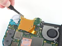
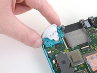
Use the point of a spudger to pry the battery connector straight up and out of its socket on the motherboard.
Caution the connector may not be properly soldered onto the motherboard. For me it snapped off the pins and now have to find a place to get that fixed if even possible. may have bricked it.
Yup, broke the connector right off the motherboard. Thanks, ifixit -_-
I backed out when I reached this point. I couldn't risk damaging it. Do u just need to pull it up? Did you mean that it might have been soldered shut below?
You should just need to pull straight up, but make sure you’re pulling on the wires or the gray plug—do not pull on the black socket or it can snap off of the motherboard.
I pulled straight up from the south side on under 2 or three wires and held down the device as I pulled and the gray connector disconnected from the black connector on the Switch. Just be careful at this part.
With how easy it seems to be to do serious damage at this point, I figured I'd say that realistically you can skip steps 9-13 when doing this repair. While they provide a bit of extra security by disconnecting the battery, the left stick is completely accessible and replaceable without touching the heat shield or anything underneath (And steps 17 and 18 disconnect power from the daughter board regardless).
just broke my connector... ifixit PLEASE put a warning on how fragile the solder on this connector is.
Note for this step, you do not need to apply a lot of force. I used two tools here: small screwdriver to hold down the black base, and one side of fine-tipped tweezers to get under all 3 wires. Gently, push down on the tweezers to push the wires upwards, which should force the gray connector up and off the base. It did not take a lot of force. Take your time and it will be fine. Again, like others have said, do NOT pull or pry up the black base.
-
-
-
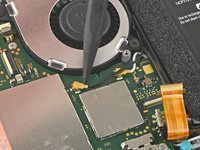
Use the flat end of a spudger or your fingers to carefully peel up the foam that's lightly adhered to the fan.
When reassembling, the foam may fold down between the fan and heatsink, blocking airflow. Gently lift the foam back up on top of the fan. The adhesive film should hold the foam together.
Is removing the heat sink absolutely necessary?
It’s not necessary, but it makes it much easier to remove and replace the game card reader, since the heat sink partially covers the connector.
Not really…….. I never remove it. It slides out quite easily once disconnected.
What do you do if these screws are stripped? They strip easily
-
-
-
Use a JIS 000 driver or an official iFixit PH 000 driver to remove the three 3 mm screws securing the heat sink to the motherboard.
Non le tre ventole ma le tre viti
Grazie per avercelo segnalato! Ho apportato la modifica. iFixit è una wiki, quindi ogni utente può modificare le pagine: se trovi altri errori in futuro, sentiti libero di fare la modifica tu stesso!
-
-
-
Use a spudger or your fingers to lift the heatsink up and off of the motherboard to remove it.
16.5 remove cartridge / headphones jack……….
I've read that there are different ways to apply thermal paste, which should I use?
My kit did not come with thermal paste..
-
-
-
Use an opening tool or your fingernail to flip up the small, hinged locking flap on the game card reader cable's ZIF connector.
-
-
-
Use a JIS 000 driver or an official iFixit PH 000 driver to remove the seven 3.1 mm screws securing the game card reader and headphone jack.
-
-
crwdns2935267:0crwdne2935267:0Tweezers$4.99
-
Use a pair of tweezers or your fingers to carefully lift the game card reader and maneuver it to the left to slide the cable out of its connector.
-
Remove the game card reader and headphone jack.
-
-
-
Use a JIS 000 driver or an official iFixit PH 000 driver to remove the two 4.5 mm screws securing the right trigger button assembly to the motherboard.
I think a whole step to remove the game card reader and speaker jack was skipped here…
yes, just found that sadly these comments do not show unless we click on the , which is unhelpful
also, you need to remove the left trigger button
No you don't actually as left trigger button is not obstructing the motherboard. Left trigger button sits on seperate board.
-
-
-
Remove the right trigger button assembly.
-
-
crwdns2935267:0crwdne2935267:0Tweezers$4.99
-
Use a pair of tweezers or your fingers to remove the right trigger button assembly's rubber pad if it didn't stay attached to the button assembly.
-
-
-
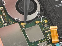
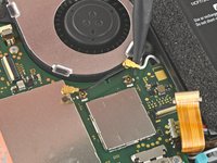
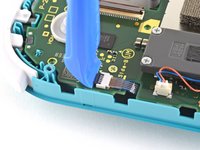
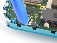
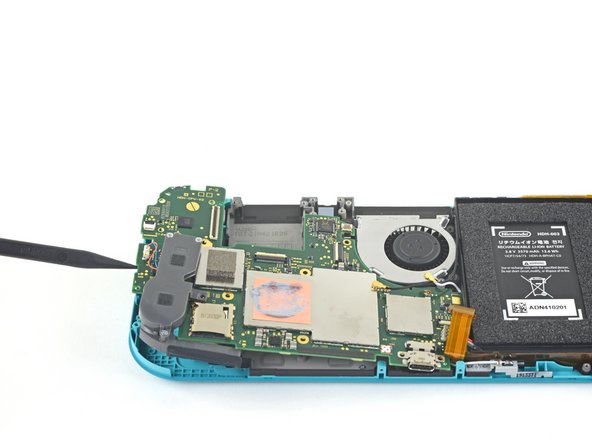
Use the point of a spudger to pry the black antenna cable straight up out of its socket on the motherboard.
-
Repeat the same process for the white antenna cable.
-
-
-
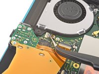
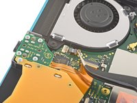
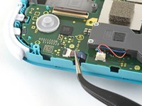
Use an opening tool or your fingernail to flip up the small, hinged locking flap on the fan cable's ZIF connector.
-
-
-
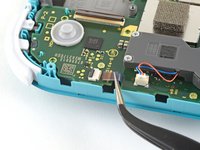
Use a pair of tweezers to slide out the fan cable from its connector on the motherboard.
There’s a step missing after this to remove the screws that hold the orange game cartridge slot. Those 7 screws have to be undone and the ribbon unclipped first before moving on to the next step.
Good Looking out!
-
-
-
Use an opening tool or your fingernail to flip up the small, hinged locking flap on the screen cable's ZIF connector.
skipped a step or two about removing the golden piece in the photo above, and the other little board
If I broke the clasp on the ZIF connector can I elec tape it down?
What did you do to fix it if the ZIF connector broke?? Mine did too and I worry that is why the screen won’t turn on now
Missing the card reader + audio jack board removal. Just remove the 4 screws around the audio jack + 3 screws around the card reader and disconnect the ZIF connector from the motherboard.
-
-
-
Use a pair of tweezers to slide the screen cable out of its connector on the motherboard.
-
-
-
Use an opening tool or your fingernail to flip up the small, hinged locking flap on the digitizer cable's ZIF connector.
-
-
-
Use a pair of tweezers to slide the digitizer cable out of its connector on the motherboard.
-
-
-
Use an opening tool or your fingernail to flip up the small, hinged locking flap on the right joystick cable's ZIF connector.
-
-
-
Use a pair of tweezers to slide the right joystick cable out of its connector on the motherboard.
-
-
-
Use a JIS 000 driver or an official iFixit PH 000 driver to remove the following six screws securing the motherboard:
-
Three 3.1 mm screws
-
Three 4.5 mm screws
how to get the c port off
When re-assembling, be sure the fan cable (step 25) is completely pulled through prior to tightening the screw that’s right next to it.
-
-
-
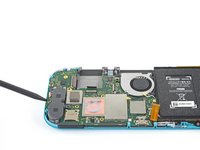
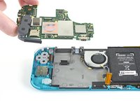
Insert a spudger in the gap between the frame and the motherboard and lift the motherboard up and out of its recess.
-
Remove the motherboard assembly.
-
-
-
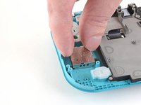
Use a JIS 000 driver or an official iFixit PH 000 driver to remove the two 3.5 mm screws securing the joystick.
-
-
-
Use your fingers to remove the joystick.
-


To reassemble your device, follow these instructions in reverse order.
Take your e-waste to an R2 or e-Stewards certified recycler.
Repair didn’t go as planned? Try some basic troubleshooting, or ask our Nintendo Switch Lite Answers community for help.
To reassemble your device, follow these instructions in reverse order.
Take your e-waste to an R2 or e-Stewards certified recycler.
Repair didn’t go as planned? Try some basic troubleshooting, or ask our Nintendo Switch Lite Answers community for help.
crwdns2935221:0crwdne2935221:0
crwdns2935229:076crwdne2935229:0

crwdns2947412:028crwdne2947412:0
Not for the faint of heart and will take much longer than the indicated time. In the end bring it to a professional, as the battery does NOT come off as indicated. I now have an even more expensive repair as the battery socket came off the motherboard.
This is for a joy stick repair...
No Name -
This looked a bit daunting at first, but as you start going you get into a flow and as long as you follow the instructions slowly and carefully you shouldnt have a problem. I would say i finished in the recommended time.
Great guide - completed with no issues easily within the recommended time.
I did not need to take out the heat sink. It’s a bit difficult. I used this guide and another to replace both buttons.
What did u do so u didn’t need to remove the heat sink? I really dknt want to remove it so I don’t disturb my thermal paste and I don’t want to replace it since I it’s kind of expensive and I dknt want to spend much money doing this repair
Minor orange juice spill on the rights side, cleaned it quick but the home button and joy stick were a little sticky.
Thank god this guide was so clear, made it easy to check the board for stains and clean up the buttons.
I had to replace my right Joy Stick and it went extremely smooth with these instructions.
Easy to repair with the correct tools. I found the time estimation to be about right. All around an easy repair, just take your time and be careful to keep the screws organized.
Broke my Switch Lite during Step 30 using my fingernail as suggested to flip the switch. It just sheared right off. Now I have a very expensive brick and a fix I paid for that broke it. I am a woman with average-sized hands and grip strength.
Super easy and helpful. Got it done in no time. I can't believe how simple this was to do.
Excellent guide. I had 2 to repair; completed the first in 45 minutes, and the second in 30!
We replaced both joysticks on my son's Switch Lite, but it will not turn back on now. I went back step by step to confirm everything was connected correctly & put it on the charger, but it will not power on at all. Any suggestions on what I can do?
any update on it because it happend to me
I did all of the intrusions and now the switch wont turn on ?
Probably a loose connection with one of the ribbon cables. unplug and replug, all ribbon cables you have unplug by doing this tutorial and check if you have well reconnect all
Nothing -
Did you ever get this resolved? Same thing happening on my end. Replaced the joy sticks but now it won’t turn on.
How am I the first to notice this?? But there is a critical part missing out of the guide! Its between step 25 and 26. if you look at 25 you can see the cartridge slot intact, (the burnt orange looking thing in the pic), and on step 26 it has magically disappeared with no instruction on how to remove it. Hopefully Ill be able to get it back together because there a cable on the underside of the pcb next to it that needs removed. anyway, proceed with caution
bc im an idiot and missed step 18 somehow, sorry ppl, feel free to remove this post mods
Does the replacement part come with an amiibo (NFC) Reader?
I repeated each step several times but the result is always the same: everything works but black screen, I don't understand what it could be, the screen flex seems intact and inserted correctly. The rest works because if I click the keys and touch I get tactile feedback. Ideas?
I replaced both sticks twice and left one still has drift and the right one is not even working 🤦♂️don’t know what to try next, any ideas?
You need to recalibrate the new joystick.
I made a mistake after placing back the mother board. On step 32 (going backwards), I accidentally screwed the flex cable for the fan. I was only able to notice it when I can't pull it back up for step 25. Other than that, the rest went smoothly given that it was my first time doing a repair. Thank you for this guide! (For my fellow DIY peeps, please don't make the same mistake as I did!)
This was so satisfying to fix. I’d never taken apart an electronic machine before and put it back together. Now I’m inspired to always try to repair before I replace.
Changed both sticks with one go - perfect guide(s)
Is there going to be more color options, I like the white on the original ones?
I think it would be good to remind newbies like me that you have to recalibrate the jostiks after replacing them. I was scared when I saw that my new jostiks were drifting.
All my screws got stripped any ideas on how to remove?
Almost A Mammal - crwdns2934203:0crwdne2934203:0
A Y0 screwdriver seemed to work better for me.
Tommy Morrill - crwdns2934203:0crwdne2934203:0
What type of screw driver do I use to un screw the screws and which way
Luca Capito - crwdns2934203:0crwdne2934203:0
Y 0.6 was all I had but it seemed to fit perfectly
Trevor - crwdns2934203:0crwdne2934203:0
Like really snug? I've gotten away with using Drivers either bigger or smaller but I hate doing it. But if 0.6 is the exact size I need, then I'll get that. I don't wanna strip my client's Switch Lite's screws.
Vincent Valodze -