crwdns2915892:0crwdne2915892:0
Follow this guide to replace a faulty or damaged motherboard in the Nintendo Switch Lite.
The Switch Lite uses JIS screws, but you can use a Phillips screwdriver in a pinch. Be very careful not to strip the screws. iFixit's Phillips bits are designed to be cross-compatible with JIS-style screws.
Note: This procedure requires removing the shield plate and heat sink. The thermal paste will need to be cleaned off of both components—as well as the CPU—and reapplied before reinstalling the shield plate and heat sink.
crwdns2942213:0crwdne2942213:0
-
crwdns2935267:0crwdne2935267:0Magnetic Project Mat$19.95
-
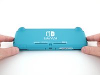
Use a Y00 screwdriver to remove the four 6.3 mm-long screws securing the back panel.
-
-
-
Use a JIS 000 driver or an official iFixit PH 000 driver to remove the following screws securing the back panel:
-
Two 3.6 mm-long screws on the top of the device
-
Two 3.6 mm-long screws on the bottom of the device
-
-
-
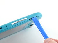
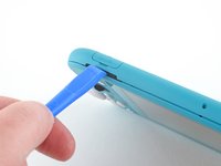
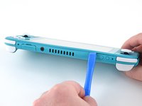
Insert an opening tool into the left speaker grille on the bottom of the device.
-
Twist the opening tool to release the clips securing the back panel.
-
-
-
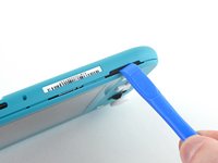
Slide the opening tool around the bottom-left corner to release the clips on the left side of the device.
-
-
-
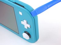
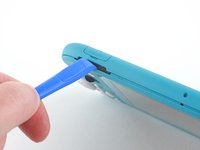
Insert an opening tool into the right speaker grille on the bottom of the device.
-
Twist the opening tool to release the clips.
-
-
-
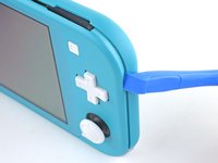
Slide and pry the opening tool around the bottom-right corner to release the clips on the right side of the device.
-
-
-
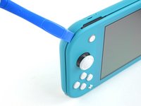
Continue sliding and prying the opening tool along the gap on the top of the device to release the clips.
-
-
-
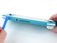
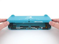
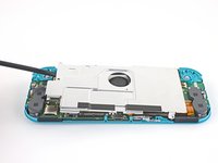
Lift the bottom edge of the back panel, opening it like a book.
-
Remove the back panel.
-
-
-
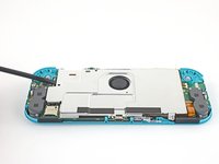
Use a JIS 000 driver or an official iFixit PH 000 driver to remove the following four screws:
-
Three 3.1 mm screws
-
One 4.5 mm screw
-
-
-
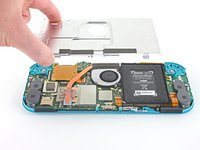
Use a spudger or your fingers to lift the shield plate up and out of the device.
-
Remove the shield plate.
-
-
-
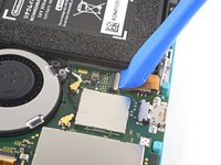
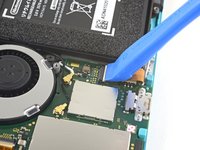
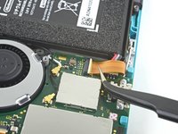
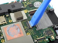
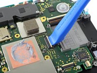
Use an opening tool or your fingernail to flip up the small, hinged locking flap on the motherboard interconnect cable's ZIF connector.
-
-
-
-
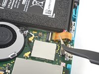
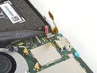
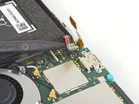
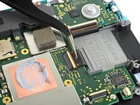
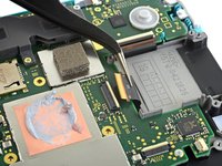
Use a pair of tweezers to slide the interconnect cable out of its connector on the motherboard.
-
-
-
Use the point of a spudger to pry the battery connector straight up and out of its socket on the motherboard.
-
-
-
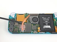
Use the flat end of a spudger or your fingers to carefully peel up the foam that's lightly adhered to the fan.
-
-
-
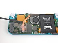
Use a JIS 000 driver or an official iFixit PH 000 driver to remove the three 3 mm screws securing the heat sink to the motherboard.
-
-
-
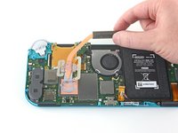
Use a spudger or your fingers to lift the heatsink up and off of the motherboard to remove it.
-
-
-
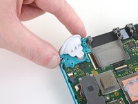
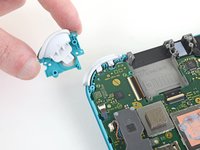
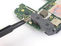
Use a JIS 000 driver or an official iFixit PH 000 driver to remove the two 4.5 mm screws securing the right trigger button assembly to the motherboard.
-
-
-
Remove the right trigger button assembly.
-
-
crwdns2935267:0crwdne2935267:0Tweezers$4.99
-
Use a pair of tweezers or your fingers to remove the right trigger button assembly's rubber pad if it didn't stay attached to the button assembly.
-
-
-
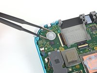
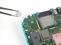
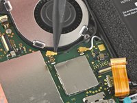
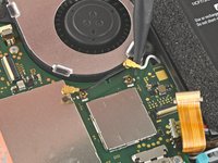
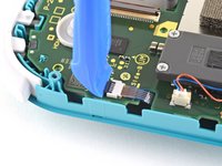
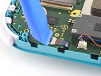
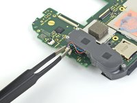
Use the point of a spudger to pry the black antenna cable straight up out of its socket on the motherboard.
-
Repeat the same process for the white antenna cable.
-
-
-
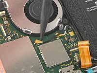
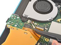
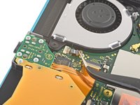
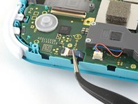
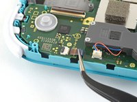
Use an opening tool or your fingernail to flip up the small, hinged locking flap on the fan cable's ZIF connector.
-
-
-
Use a pair of tweezers to slide out the fan cable from its connector on the motherboard.
-
-
-
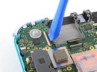
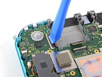
Use an opening tool or your fingernail to flip up the small, hinged locking flap on the screen cable's ZIF connector.
-
-
-
Use a pair of tweezers to slide the screen cable out of its connector on the motherboard.
-
-
-
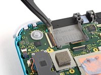
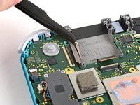
Use an opening tool or your fingernail to flip up the small, hinged locking flap on the digitizer cable's ZIF connector.
-
-
-
Use a pair of tweezers to slide the digitizer cable out of its connector on the motherboard.
-
-
-
Use an opening tool or your fingernail to flip up the small, hinged locking flap on the right joystick cable's ZIF connector.
-
-
-
Use a pair of tweezers to slide the right joystick cable out of its connector on the motherboard.
-
-
-
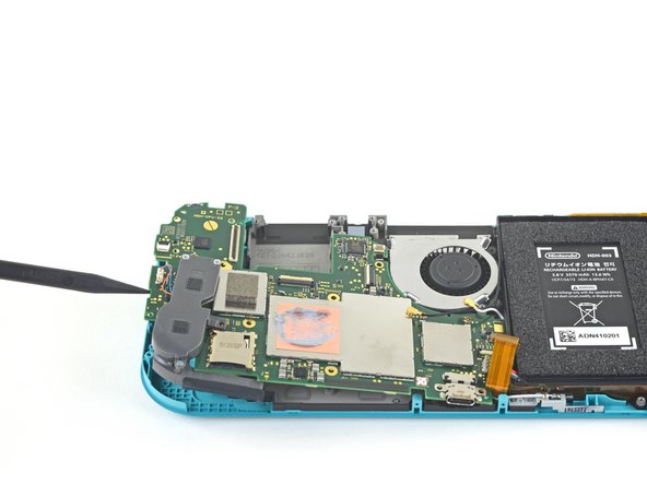
Use a JIS 000 driver or an official iFixit PH 000 driver to remove the following six screws securing the motherboard:
-
Three 3.1 mm screws
-
Three 4.5 mm screws
-
-
-
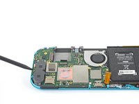
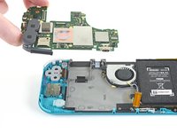
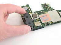
Insert a spudger in the gap between the frame and the motherboard and lift the motherboard up and out of its recess.
-
Remove the motherboard assembly.
-
-
crwdns2935267:0crwdne2935267:0Tweezers$4.99
-
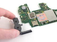
Use a pair of tweezers or your fingers to pull the right speaker cable straight up and out of its socket on the motherboard.
-
-
-
Remove the right speaker module from the motherboard.
-


To reassemble your device, follow these instructions in reverse order.
Take your e-waste to an R2 or e-Stewards certified recycler.
Repair didn’t go as planned? Try some basic troubleshooting, or ask our Nintendo Switch Lite Answers community for help.
crwdns2935221:0crwdne2935221:0
crwdns2935229:024crwdne2935229:0

crwdns2947412:08crwdne2947412:0
Great guide, helped me fix charge port replacement, did notice between 16-17 the card reader magically disappeared, but help me tear down and repair and rebuild with a little bit of head scratching.
La guida è molto chiara.. ma dove si può acquistare una scheda madre di ricambio ?
It stops at motherboard removal, is there a section for replacing the USB charging port on the switch lite?
Where can i get the motherboard from, i cant replace the charging port, cause it is soldered to the motherboard. So if you could please let me know onto where i can get the mother board from. 😊
I have a working motherboard but it is missing one of the resistors (see the green square). How do I find out the value of this resistor? The resistor is situated to the left of the main chip, just below the microSD card slot, if the USB-C port is facing downward.