crwdns2915892:0crwdne2915892:0
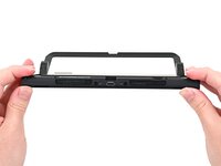
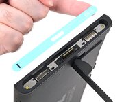
Follow this guide to replace the back cover on a Nintendo Switch 2 game console.
The Switch 2 uses JIS screws. If you use a non-iFixit Phillips driver in JIS screws, you'll risk stripping them. iFixit's Phillips bits are designed to be compatible with JIS screws.
crwdns2942213:0crwdne2942213:0
-
-
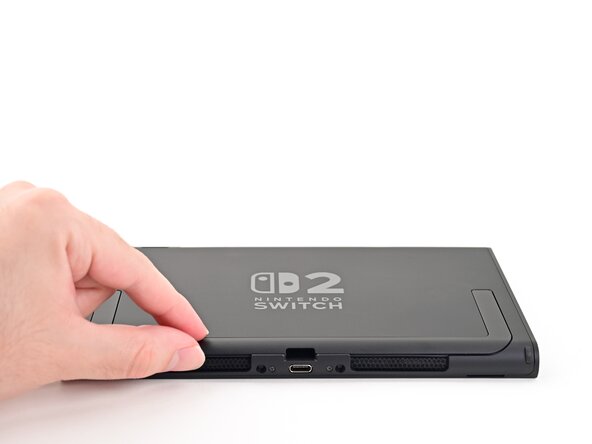
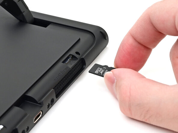
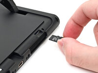
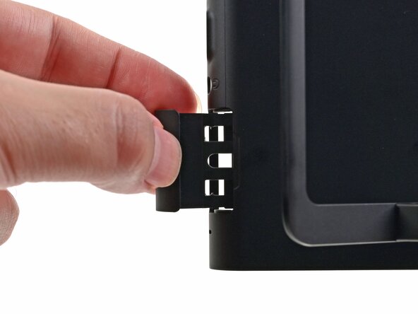
Remove any game cards and disconnect any cables, controllers, or other accessories from the console.
-
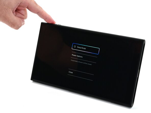
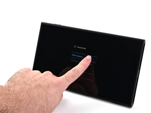
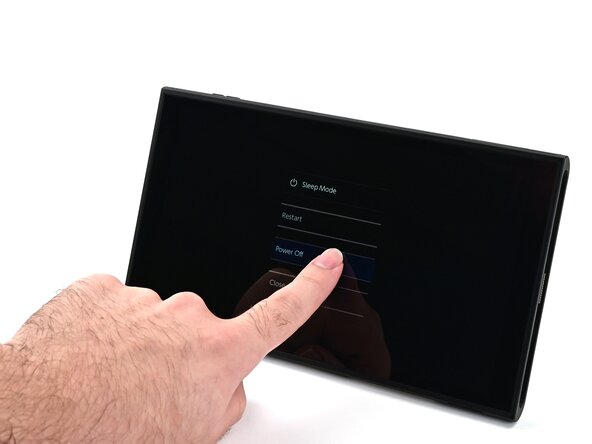
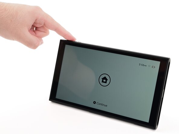
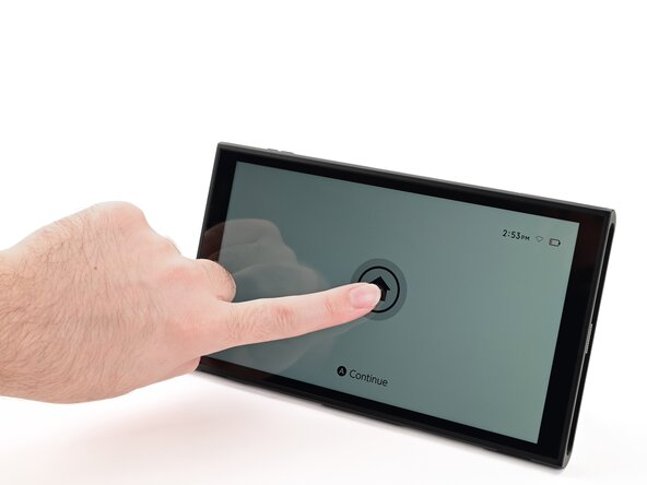
Power off the console by holding down the power button, selecting Power Options, then pressing Power Off.
-
-
-
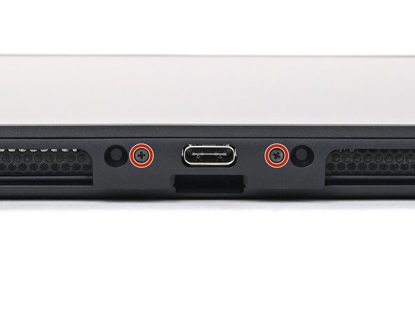
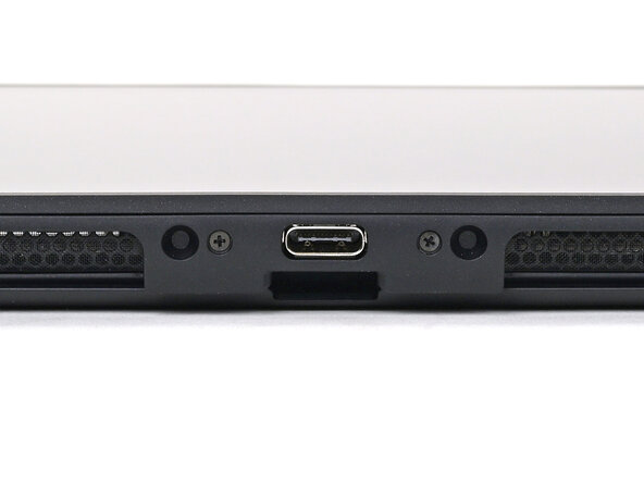
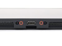
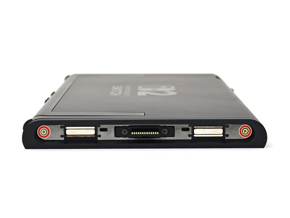
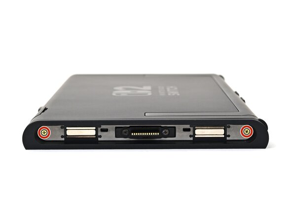
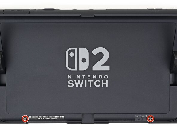
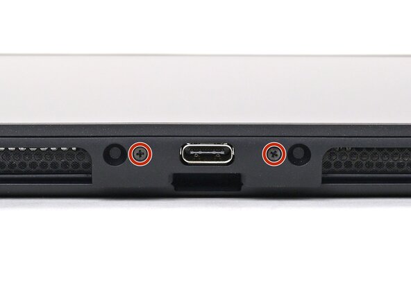
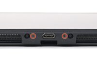
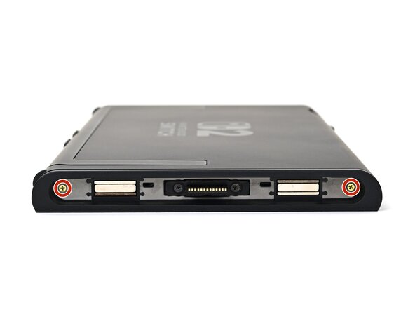
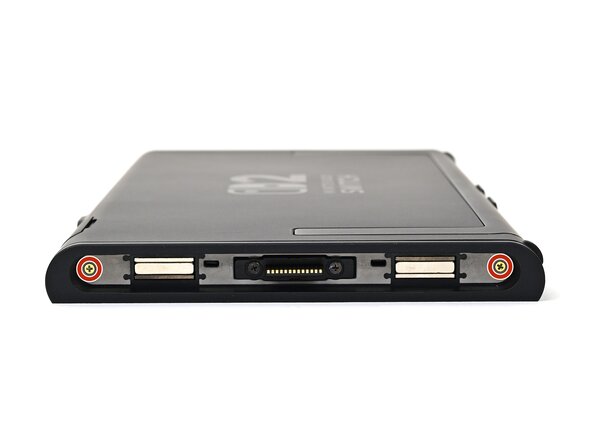
Use a JIS 00 driver to remove the two 3.1 mm‑long screws on either side of the bottom USB-C port.
-
-
-
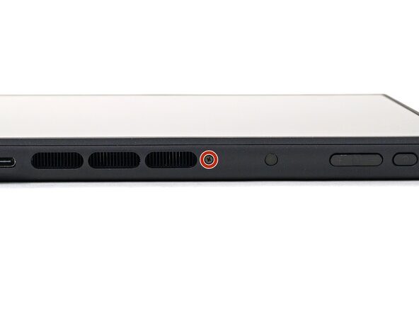
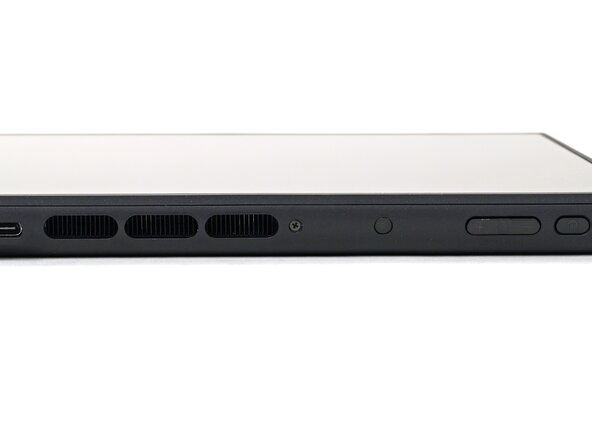
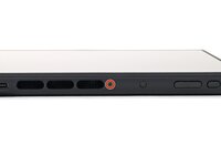
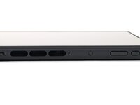
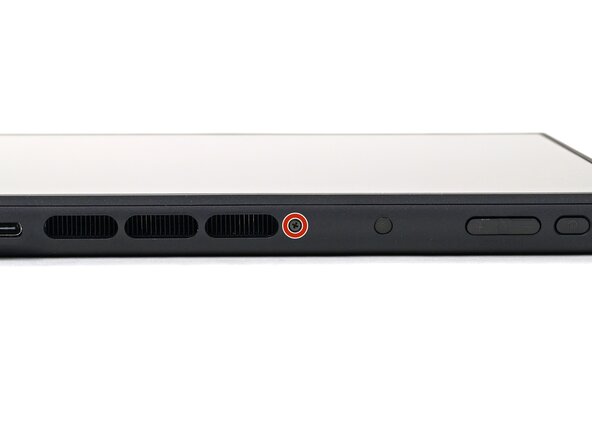
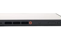
Use a JIS 00 driver to remove the 3.1 mm‑long screw on the top edge of the console (next to the ventilation cutouts).
-
-
-
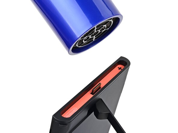
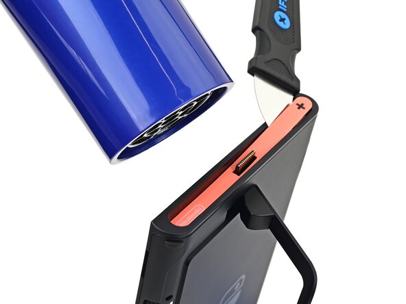
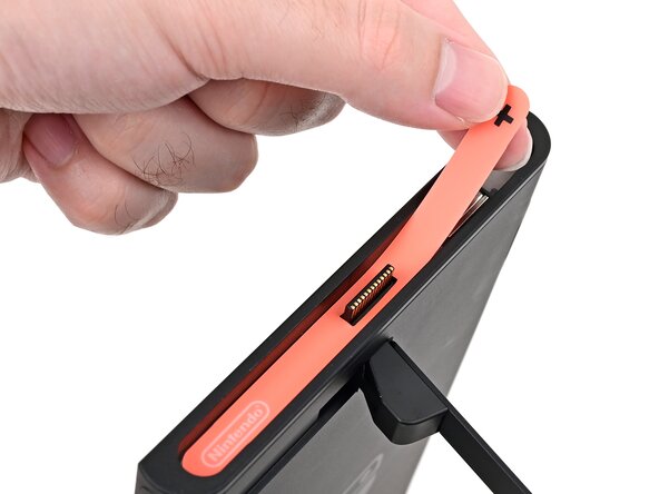
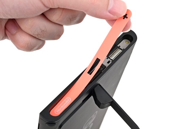
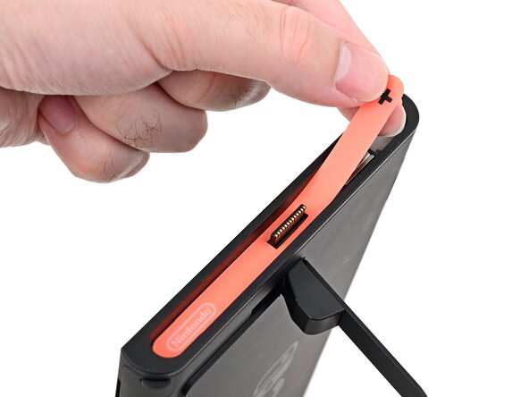
Use a hair dryer or heat gun to heat the sticker on the right side of the console, labeled with a "+" symbol, until it's hot to the touch.
-
-
-
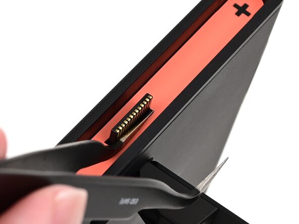
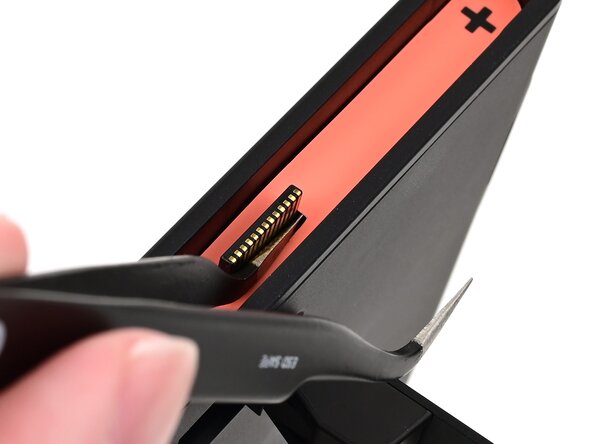
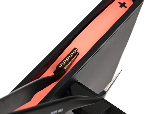
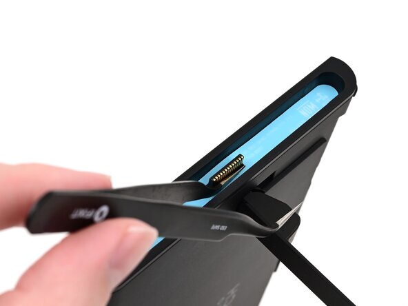
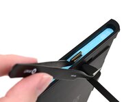
Slide one arm of angled tweezers underneath the sticker from its cutout around the right Joy‑Con 2 connector.
-
Gently pry up on the sticker until it starts to lift from the console.
-
Leave the tweezers in place to keep the sticker lifted.
-
-
crwdns2935267:0crwdne2935267:0Jimmy$7.95
-
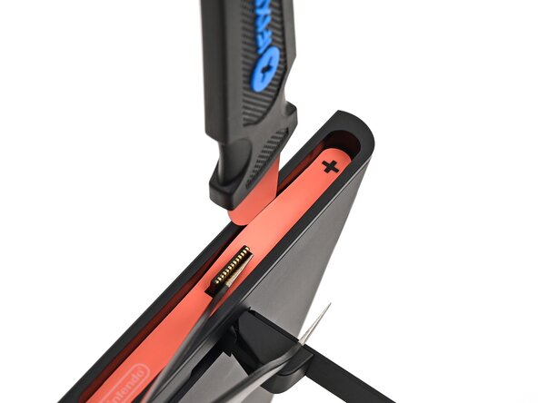
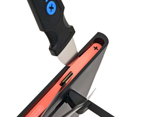
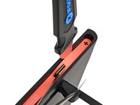
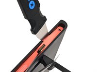
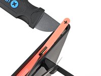
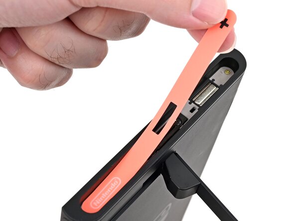
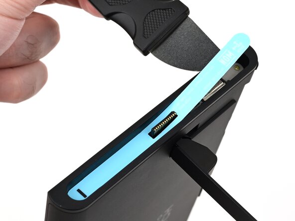
Insert the tip of a Jimmy into the gap formed between the long edge of the console and the sticker.
-
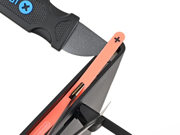
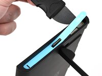
Gently pry up the sticker, working your way up the long edge until the top of the sticker is separated from the console.
-
Remove the tweezers once the sticker is lifted.
-
-
-
Reheat the bottom of the right side until it's hot to the touch.
-
-
-
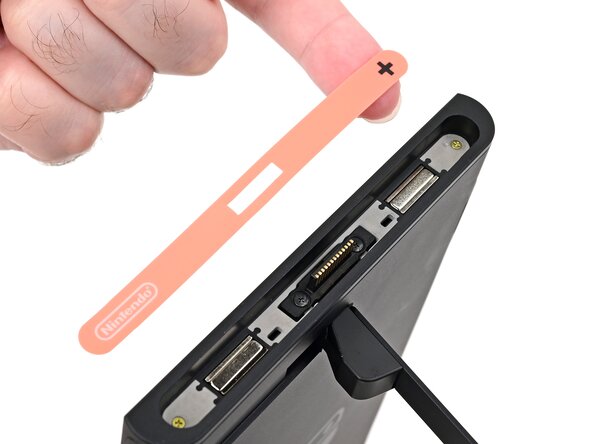
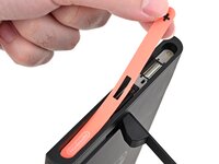
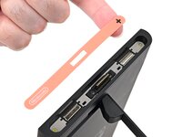
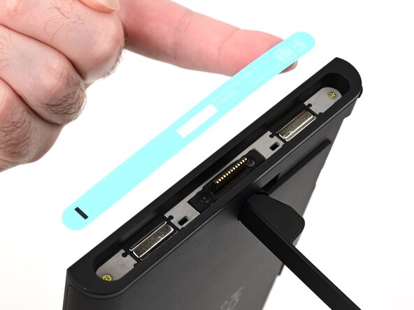
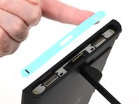
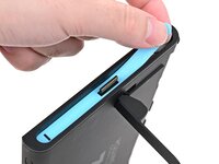
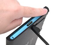
Carefully lift the sticker over the Joy‑Con 2 connector, then peel it up fully to remove it.
-
-
-
Repeat this procedure to remove the sticker along the left side of the console, labeled with a "-" symbol.
-
-
-
-
Use a JIS 00 driver to remove the two 3.6 mm‑long gold screws on each side of the console (four in total).
-
-
-
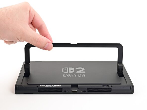
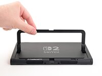
Use your fingers to flip up the kickstand on the back of the console.
-
-
-
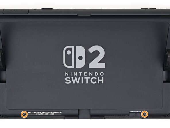
Use a Y00 driver to remove the two 4.4 mm‑long screws in the kickstand cutout.
-
-
-
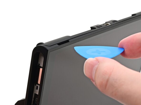
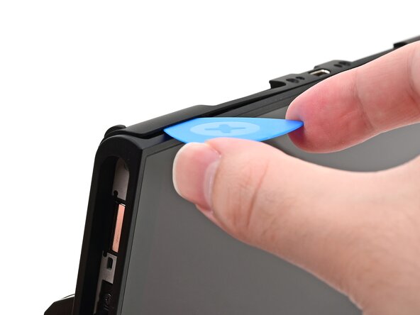
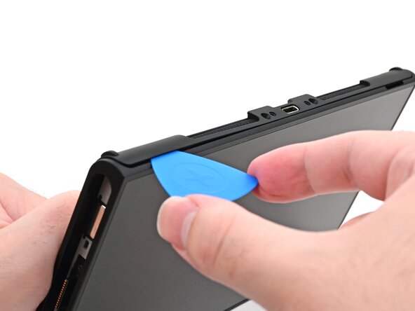
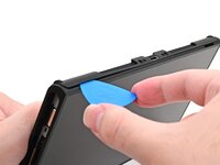
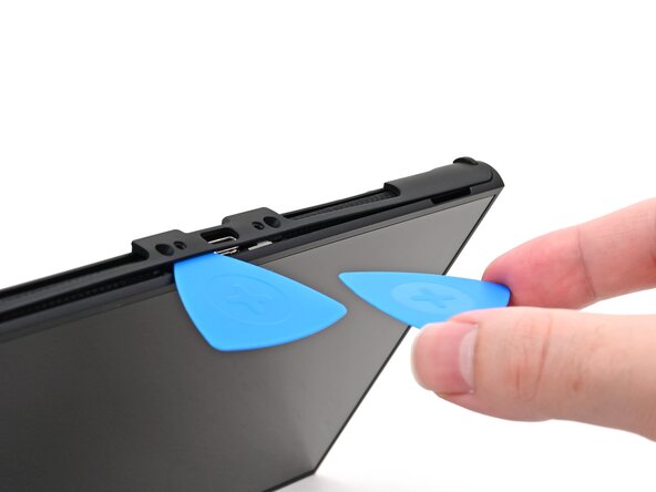
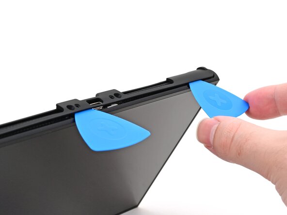
Insert an opening pick into the gap between the back cover and speaker cutout on the bottom edge of the console.
-
-
-
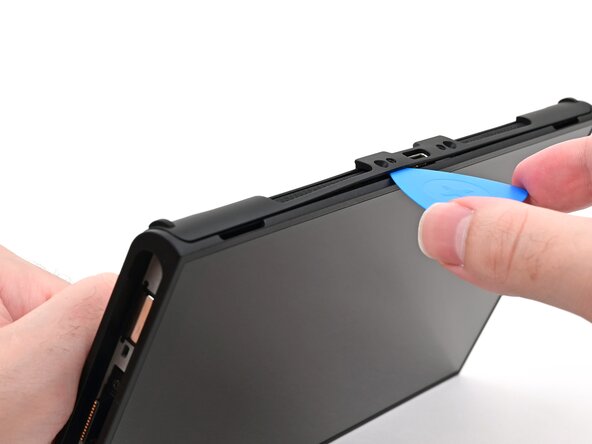
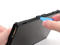
Slide the opening pick towards the USB-C port until it's underneath the screw hole next to the port.
-
-
-
Insert a second opening pick underneath the screw hole on the opposite side of the USB-C port, and slide it to the corner of the console.
-
-
-
Slide the first opening pick back to where it was first inserted.
-
-
-
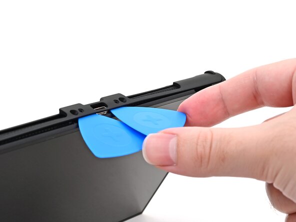
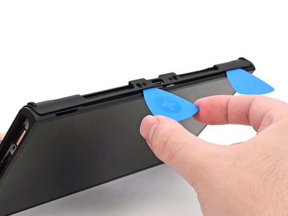
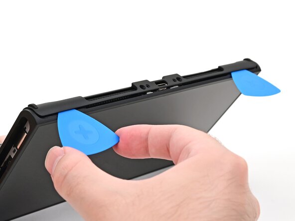
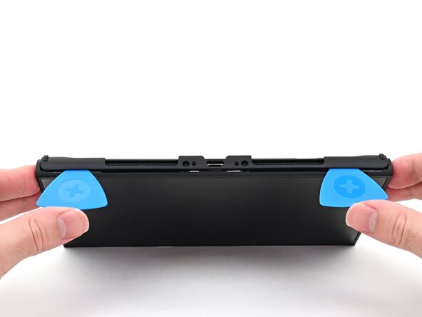
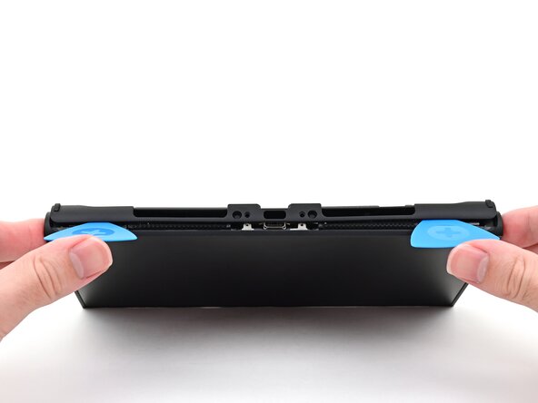
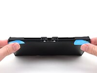
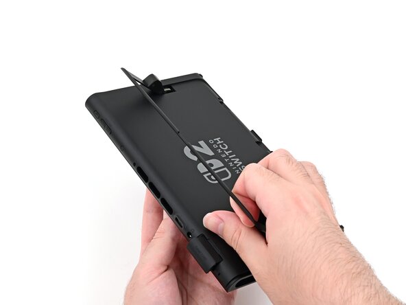
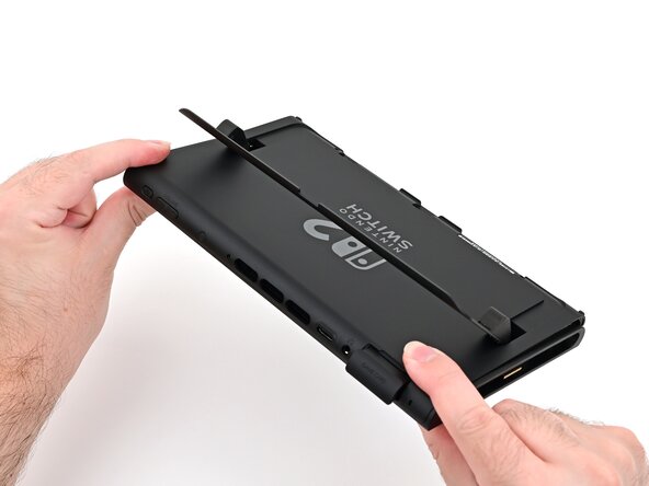
Hold the console with two hands. Rest your thumbs on the opening picks.
-
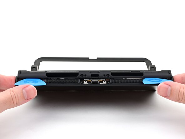
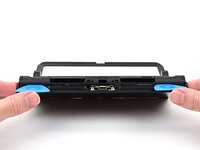
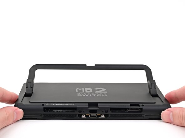
Push up on the opening picks to lift the back cover until it pops up above the USB-C port.
-
-
-
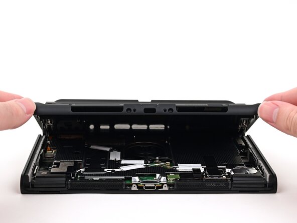
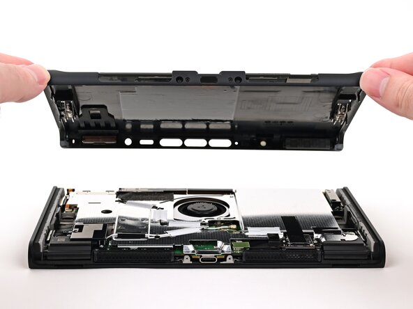
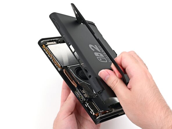
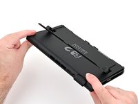
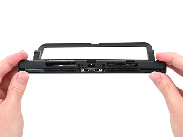
Lift the back cover up from the bottom edge and remove it.
-
-
-
Congratulations on completing disassembly! The remaining steps will show how to reassemble your console.
-
-
-
Fully pull out the game card tray.
-
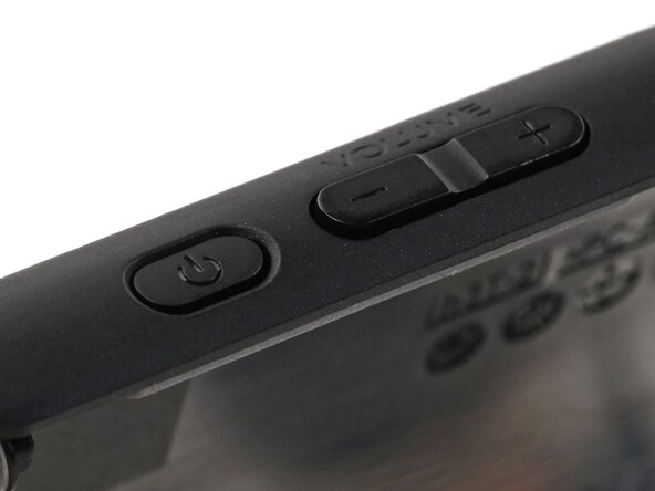
Double-check the power and volume buttons to ensure they're seated correctly. If the rubber membrane beneath the buttons is out of place, ensure it's aligned with its pegs.
-
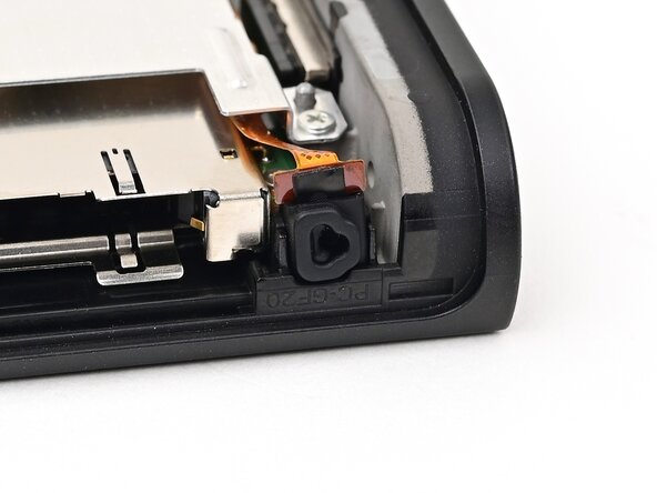
Check the microphone to ensure it's fully seated in its slot in the frame.
-
-
-
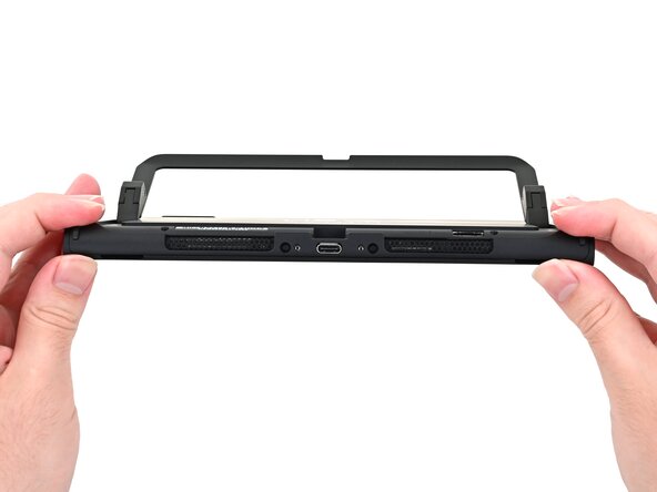
Align the top of the back cover with the top of the console.
-
Set the top edge of the back cover into place, checking the buttons and ports to ensure they're aligned properly. If they aren't, lift the back cover and try again.
-
Press along the top edge to fasten the clips securing the back cover to the console.
-
-
-
Squeeze the rest of the back cover and console together to fasten the clips.
-
-
-
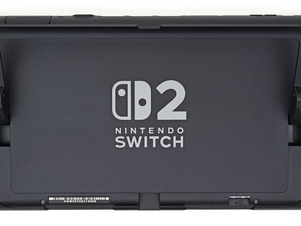
Use a JIS 00 driver to install the three 3.1 mm‑long screws securing the back cover: one on the top edge of the console, and two on either side of the bottom USB-C port.
-
Use a Y00 driver to install the two 4.4 mm‑long screws in the kickstand cutout.
-
-
-
Install the two 3.6 mm‑long gold screws on each side of the console (four in total).
-
-
-
Power on the console and test functionality to ensure it's working as expected.
-
-
-
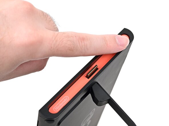
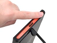
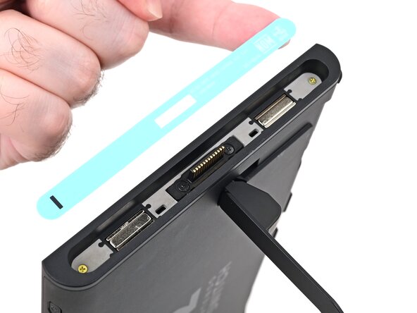
Align the right side sticker with its recess. Ensure the cutout in the sticker is aligned with the Joy-Con connector.
-
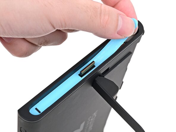
Set the sticker into its recess, first on one side, then the other.
-
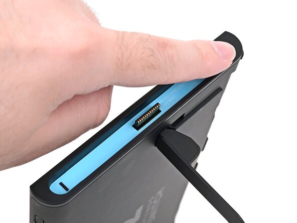
Use your finger or the flat end of a spudger to press the sticker into place.
-
-
-
Repeat this procedure to install the left side sticker.
-
You finished fixing your Switch 2!
Repair didn’t go as planned? Try some basic troubleshooting, or ask our Nintendo Switch 2 Answers Community for help.
