crwdns2915892:0crwdne2915892:0
Use this guide to replace the shutter assembly.
Note: You'll need JIS screwdrivers for this repair. Regular Phillips screwdrivers have a cross pattern with rounded inner edges and won't fully fit the slots in the JIS screws. JIS screwdrivers instead have a straight cross pattern which makes much better contact with the screw head and is made for the high torque you will need to loosen the screws.
crwdns2942213:0crwdne2942213:0
-
-
Remove the following 5 screws securing the bottom cover to the camera body:
-
Four 6 mm J000 screws.
-
One 8 mm J000 screw (under lens mount).
-
-
-
Remove three 6 mm J000 screws from under the battery cover.
Note for D7100: the screw marked red closest to the yellow battery guarding clip is 5.3mm long, the 2 other screws marked red are 6.0mm long.
-
-
-
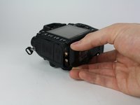
Gently pull the bottom cover off of the camera body.
Note for D7100: place your thumb in the battery compartment and your index outside the battery box. Gently pinch the bottom cover between thumb and index finger, and gently lift it from the camera body. It separates very easily.
-
-
-
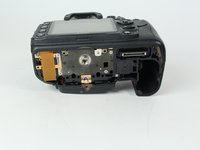
Remove the following screws from the port area:
-
Two 3.5 mm J000 screws.
-
One 6 mm J000 screw (right above ports).
Note for D7100: the 2 screws marked red under the rubber covers are hidden below the middle cover. These screws are 3.8mm long. The orange screw is 6.35mm long.
-
-
crwdns2935267:0crwdne2935267:0Tweezers$4.99
-
Peel the rear rubber piece off with tweezers.
This is not needed : if you don't touch this rubber & screw the SD card cover will come off at the same time that the back case.
= Quicker and easier
-
-
-
Remove one 4.25 mm J000 screw from behind the rear rubber piece.
This is not needed : if you don't touch this rubber & screw the SD card cover will come off at the same time that the back case.
= Quicker and easier
⚠️ Note for D7100: this step IS needed when disassembling the D7100 body as the rubber conceals 2 JIS #000 screws (5.5 mm at top and 3 mm at bottom). Without removing those 2 screws the back case won't separate from the body. When detaching the rubber cover, make sure to keep the small plastic cover embedded at the bottom of the rubber.
The SD card cover will fall out from the camera body when separating the back case.
-
-
-
Pull the eyepiece cover up to remove it.
-
-
-
Remove two 6 mm J000 screws from behind the eyepiece cover.
Concerning the diopter, it's wrong : D7000 also have a screw in it.
See step 41.
Note for D7100: the 2 screws to the side of the eyepiece are 5.3mm long.
Note for D7100: the screw holding the diopter dial is 11.4mm long.
-
-
-
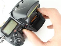
Open the SD card cover by pushing slightly down with your thumb and sliding up.
-
-
-
Remove four 6 mm J000 screws that secure the SD card cover.
Note for D7100: these 4 screws are 6.30-6.35mm long
Los 4 tornillos miden 5mm en la D7000
-
-
-
Gently pull the SD card cover off.
Attention! High voltage. After removing the memory card cover, remove the yellow sticker and use a 220 volt 15 watt incandescent lamp to discharge the capacitor.
-
-
-
Remove the following screws that secure the back case:
-
One 6 mm J000 screw.
-
One 3 mm J000 screw.
On D7100 both screws are the same length at 6mm
En la D7000 ambos miden 4mm
-
-
-
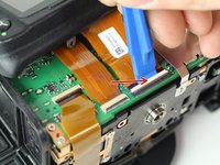
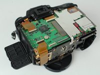
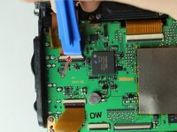
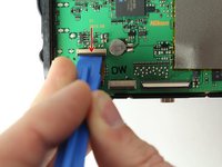
Disconnect the following two ribbon cables from the motherboard.
Note for D7100: the 2 ribbon cables that connect the back cover to the motherboard have ZIF sockets with the black lever at the bottom. Leave the other 2 (leftmost) ribbon cables at the bottom of the motherboard untouched.
-
-
-
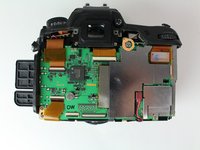
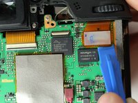
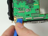
Remove the following screws securing the left motherboard shield:
-
One 2 mm J000 screw (on the bottom).
-
One 3.5 mm J000 screw (on the back).
-
-
-
Gently pry and lift the left motherboard shield off.
No need to remove shield. Risk of damaging clips holding shield.
No Motherboard shield on D7100
-
-
-
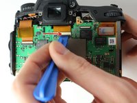
Remove one 3.5 mm J000 screw securing the right motherboard shield.
No need to remove shield. Risk of damaging clips holding shield.
-
-
-
Gently lift the right motherboard shield off with the tip of a spudger.
-
-
-
-
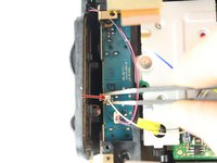
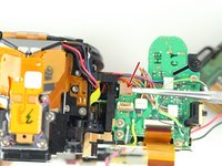
Disconnect remaining ribbon cables.
Note for D7100: at the top of the motherboard, there are 2 wide ZIF sockets (far left: white lever at top; far right: brown lever at bottom) and a narrow "no-fuss ribbon cable connector" (cable connector makes a 90° turn from 12 o' clock to 3 o'clock).
-
-
-
Disconnect remaining ribbon cables.
One more ribbon behind press down tab
Note for D7100: at the bottom of the motherboard, there are 3 ZIF sockets (far left, top: black lever at bottom; far left, bottom (underneath the previous): black lever at top; adjacent to the right: black lever at top).
-
-
-
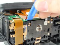
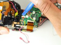
Carefully disconnect the red connector with tweezers.
-
-
-
Remove four 3.5 mm J000 screws securing the motherboard.
-
-
-
Gently pull the port side cover away from the motherboard.
-
-
-
Remove four 6 mm J000 screws securing the tripod plate.
Only left 2 screw need to be removed. The tripod plate do not need to be removed.
Actually, nothing needs to be removed !
Skip this step and gain time and energy :)
-
-
-
Carefully lift the tripod plate from the backside of the camera and slide out the grounding clip from under the lens mount.
-
-
-
Disconnect black and white speaker cable.
-
-
-
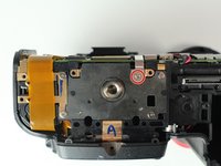
Remove three 6 mm J000 screws securing the image sensor.
Best to set markings on the three screws before removing sensor. To preserve alignment of sensor and body frame
This step is NOT necessary if you don't plan on doing anything with the sensor itself
-> just let it all attached together and save yourself time and energy
These 3 JIS #0 screws require quite some torque to unscrew.
Don't forget to open the ZIF connector of the sensor ribbon cable before removing the sensor board.
-
-
-
Carefully lift the image sensor plate out of the camera.
-
-
-
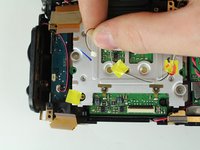
Manually pop up flash by inserting a screw driver to the left of the viewfinder and pressing on the metal lever.
-
-
-
Remove two 5 mm J000 screws from under the flash.
-
-
-
Remove two 3 mm J000 screws securing the front cover.
These screws should be the other way around. I took the 5mm screws out of the front cover. 3mm screws from under the flash.
Exactamente amigo esta alrevez la descripción
-
-
-
Remove one 4 mm J000 screw from the front.
-
-
-
Remove one 8.5 mm J000 screw from the battery compartment.
-
-
-
Remove one 4 mm J000 screw securing the top case (under right strap hook).
-
-
-
Remove one 4 mm J000 screw securing the top case (under left strap hook).
-
-
-
Remove the sticker covering the diopter adjust screw.
-
-
-
Remove one 8.0 mm J000 screw.
-
Remove the Diopeter Adjust.
-
-
-
Remove the top case.
No mention of discharging the flash capacitor first?
Make sure you don’t get a shock off it .
-
-
-
Remove the Black, Yellow, Green cable from the top case board.
If intend to remove top panel entirely, will need to de-solder the black and red power cable
-
-
-
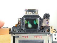
Remove two 6.5 mm J000 screws securing the viewfinder.
-
Remove the viewfinder cover.
-
-
-
Remove one 3 mm J000 screw from the bottom left side of the camera.
-
-
-
Remove two 6 mm J000 screws from the left of the shutter.
-
-
-
Remove two 6.5 mm J000 screws from beneath the lens mount.
-
-
-
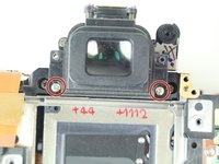
Remove two screws from just below and to the sides of the viewfinder.
-
-
-
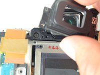
Remove one 5 mm J000 screw from the top right of the camera.
-
-
-
Carefully peel back ribbon cable on the bottom left of camera.
-
-
-
Remove the left front ribbon cable from top right of circuit board.
The illustration indicates this connector to be tilted upwards. I did - and broke the female connector. As shown on the right hand picture, the same thing has happened during the dismantling forming the basis for this “ifixit” instruction.
This ribbon should be pulled straight out - not lifted upwards
-
-
-
Separate the shutter assembly from the camera body.
This part left me in the lurch a bit, undid the top 2 screws holding the shutter in but there seemed more to undo to actually release the shutter.
If you intend to replace the shutter assembly only, you need to loosen it from the “shutter house” (don’ know correct term); (It is possible to purchase new blades only, but it seems complicated, and a shutter assembly costs around 35USD from Asia.)
There are 3 screws; 2 visible on the “top” of the shutter assembly and one hidden underneath some ribbons on the “underside”. Study the new shutter to identify the screws being part of of the assembly and the ones holding it to the shutter house. (3 screws as mentioned)
The power leads for the electric motor must be loosened by soldering (red and black cables).
A ribbon with 4 tiny soldering points has to be loosened with a sharp tipped soldering iron; If you don’ t feel competent; bring it to someone who can do the very delicate soldering - especially for connecting the new shutter assembly.
I have followed this guide. But 2 small bits of rubber have appeared. Not a clue from where. Any ideas?
When opening the shutter assembly, there are 3 small rubber parts. A larger one at the bottom left, 2 smaller ones fit in the bottom right. You'll notice rectangular slots (horizontal or at 45°). That's where they fit.
-


To reassemble your device, follow these instructions in reverse order.
To reassemble your device, follow these instructions in reverse order.
crwdns2935221:0crwdne2935221:0
crwdns2935229:035crwdne2935229:0
crwdns2915084:0crwdne2915084:0

Cal Poly, Team 24-6, Lancaster Spring 2015 crwdns2935289:0Cal Poly, Team 24-6, Lancaster Spring 2015crwdne2935289:0
CPSU-LANCASTER-S15S24G6
crwdns2931471:03crwdne2931471:0
crwdns2935297:05crwdne2935297:0
crwdns2947412:010crwdne2947412:0
Use a #00 Philips, not a #0, or you'll strip the screws. Also, there are two or three screws connecting the shutter assembly to the camera body, and its contacts are soldered on. So you need a soldering iron for the last step.
im gonna be trying this soon , how long did it take and how difficult is it ,,,
Guide not completed. Last step only shows removal of mirror box. Shutter assembly replacement not
Regardless of possibly a few missing steps, this is a great lesson of how to deal with shutter replacement on my own. Hats off !!
How to reassemble diopter adjustment?
Can anyone help me with diopter control I took it apart by accident I don’t know how to put it back- jsarmd@yahoo.com
what model cmos battery
Great that you posted link to Youtube video.
I had not been able to find the repair manual for this model and your step by step intructions helped me on the doubs I had.
Thanks.
Done mine but I do confess I got help from a mate how repairs mobile phones and computers make sure you note where all the screws go wee kept them in order when removing them so you no where thy all go when re assembling it back together I don’t think I would try to do it myself wee did take some photos helped when rebuilding it back together it worked ok after maybe wee were lucky
Where do I purchase internal parts for Nikon D series cameras? Thank you
Note for D7100: the rightmost screw marked red is 5.4mm long (to the right of the identification sticker with serial number), the 3 other screws marked red are 6.0mm long. The orange screw is 8.75mm long.
Olivier Biot - crwdns2934203:0crwdne2934203:0