crwdns2915892:0crwdne2915892:0
Use this guide to replace the shutter assembly.
Note: You'll need JIS screwdrivers for this repair. Regular Phillips screwdrivers have a cross pattern with rounded inner edges and won't fully fit the slots in the JIS screws. JIS screwdrivers instead have a straight cross pattern which makes much better contact with the screw head and is made for the high torque you will need to loosen the screws.
crwdns2942213:0crwdne2942213:0
-
-
Remove the following 5 screws securing the bottom cover to the camera body:
-
Four 6 mm J000 screws.
-
One 8 mm J000 screw (under lens mount).
-
-
-
Remove three 6 mm J000 screws from under the battery cover.
-
-
-
Gently pull the bottom cover off of the camera body.
-
-
-
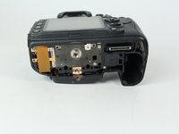
Remove the following screws from the port area:
-
Two 3.5 mm J000 screws.
-
One 6 mm J000 screw (right above ports).
-
-
crwdns2935267:0crwdne2935267:0Tweezers$4.99
-
Peel the rear rubber piece off with tweezers.
-
-
-
Remove one 4.25 mm J000 screw from behind the rear rubber piece.
-
-
-
Pull the eyepiece cover up to remove it.
-
-
-
Remove two 6 mm J000 screws from behind the eyepiece cover.
-
-
-
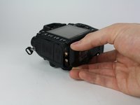
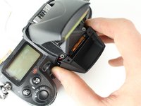
Open the SD card cover by pushing slightly down with your thumb and sliding up.
-
-
-
Remove four 6 mm J000 screws that secure the SD card cover.
-
-
-
Remove the following screws that secure the back case:
-
One 6 mm J000 screw.
-
One 3 mm J000 screw.
-
-
-
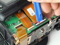
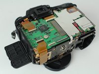
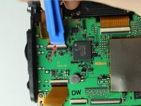
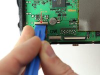
Disconnect the following two ribbon cables from the motherboard.
-
-
-
Remove the following screws securing the left motherboard shield:
-
One 2 mm J000 screw (on the bottom).
-
One 3.5 mm J000 screw (on the back).
-
-
-
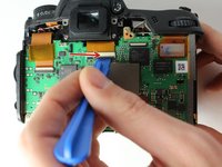
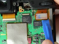
Gently pry and lift the left motherboard shield off.
-
-
-
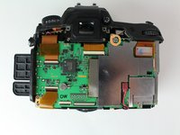
Remove one 3.5 mm J000 screw securing the right motherboard shield.
-
-
-
Gently lift the right motherboard shield off with the tip of a spudger.
-
-
-
-
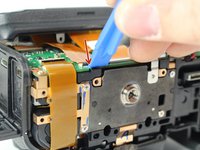
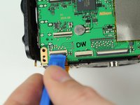
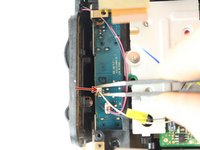
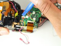
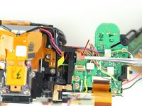
Carefully disconnect the red connector with tweezers.
-
-
-
Remove four 3.5 mm J000 screws securing the motherboard.
-
-
-
Gently pull the port side cover away from the motherboard.
-
-
-
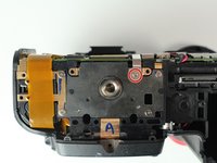
Remove four 6 mm J000 screws securing the tripod plate.
-
-
-
Carefully lift the tripod plate from the backside of the camera and slide out the grounding clip from under the lens mount.
-
-
-
Disconnect black and white speaker cable.
-
-
-
Remove three 6 mm J000 screws securing the image sensor.
-
-
-
Carefully lift the image sensor plate out of the camera.
-
-
-
Manually pop up flash by inserting a screw driver to the left of the viewfinder and pressing on the metal lever.
-
-
-
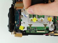
Remove two 5 mm J000 screws from under the flash.
-
-
-
Remove two 3 mm J000 screws securing the front cover.
-
-
-
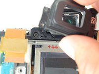
Remove one 4 mm J000 screw from the front.
-
-
-
Remove one 8.5 mm J000 screw from the battery compartment.
-
-
-
Remove one 4 mm J000 screw securing the top case (under right strap hook).
-
-
-
Remove one 4 mm J000 screw securing the top case (under left strap hook).
-
-
-
Remove the sticker covering the diopter adjust screw.
-
-
-
Remove one 8.0 mm J000 screw.
-
Remove the Diopeter Adjust.
-
-
-
Remove the Black, Yellow, Green cable from the top case board.
-
-
-
Remove two 6.5 mm J000 screws securing the viewfinder.
-
Remove the viewfinder cover.
-
-
-
Remove one 3 mm J000 screw from the bottom left side of the camera.
-
-
-
Remove two 6 mm J000 screws from the left of the shutter.
-
-
-
Remove two 6.5 mm J000 screws from beneath the lens mount.
-
-
-
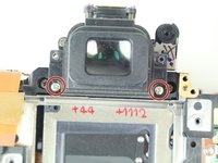
Remove two screws from just below and to the sides of the viewfinder.
-
-
-
Remove one 5 mm J000 screw from the top right of the camera.
-
-
-
Carefully peel back ribbon cable on the bottom left of camera.
-
-
-
Remove the left front ribbon cable from top right of circuit board.
-
-
-
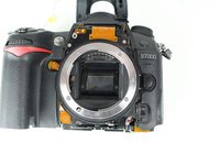
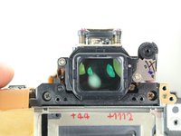
Separate the shutter assembly from the camera body.
-


To reassemble your device, follow these instructions in reverse order.
crwdns2935221:0crwdne2935221:0
crwdns2935229:035crwdne2935229:0
crwdns2935287:0crwdne2935287:0

Cal Poly, Team 24-6, Lancaster Spring 2015 crwdns2935289:0Cal Poly, Team 24-6, Lancaster Spring 2015crwdne2935289:0
CPSU-LANCASTER-S15S24G6
crwdns2931471:03crwdne2931471:0
crwdns2935297:06crwdne2935297:0
crwdns2947412:010crwdne2947412:0
Use a #00 Philips, not a #0, or you'll strip the screws. Also, there are two or three screws connecting the shutter assembly to the camera body, and its contacts are soldered on. So you need a soldering iron for the last step.
im gonna be trying this soon , how long did it take and how difficult is it ,,,
Guide not completed. Last step only shows removal of mirror box. Shutter assembly replacement not
Regardless of possibly a few missing steps, this is a great lesson of how to deal with shutter replacement on my own. Hats off !!
How to reassemble diopter adjustment?