crwdns2915892:0crwdne2915892:0
Use this guide to remove or replace the daughterboard on your Motorola Moto G7 Power.
Before you begin, download the the Software Fix app to backup your device and diagnose whether your problem is software or hardware related.
Some images may have visual discrepancies, such as the SIM card tray being removed from the phone. You don’t need to remove the SIM card tray for this procedure.
You’ll need some double-sided tape (such as Tesa tape) in order to adhere the replaced components.
For your safety, discharge the battery below 25% before disassembling your phone. This reduces the risk of a dangerous thermal event if the battery is accidentally damaged during the repair. If your battery is swollen, take appropriate precautions.
crwdns2942213:0crwdne2942213:0
-
-
Apply a heated iOpener or a heat gun to the bottom edge of the screen for approximately two minutes to help soften the adhesive.
-
-
-
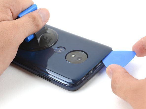
Apply a suction cup to the rear cover, as close to the heated edge as possible.
-
Pull up on the suction cup with strong, steady force to create a gap.
-
Insert an opening pick into the gap you created under the rear cover.
The suction cup did not stick on the cover, as I increasingly put force on it.
-
-
-
Slide the pick along the bottom of the gap to slice through the adhesive securing the rear cover to the midframe.
I managed to put in the picks one by one. This worked fine.
No way you can get a pick in. There is no movement at all in the cover, even if I fry the device!
-
-
-
Slide the pick along the gap on the same side of the phone as the SIM card tray to slice through the adhesive securing the rear cover to the midframe.
Just to mention it... It is a good idea not to start directly at the SIM slot...it might break.
-
-
-
Slide the pick along the gap at the top of the phone to slice through the adhesive securing the rear cover to the midframe.
-
-
-
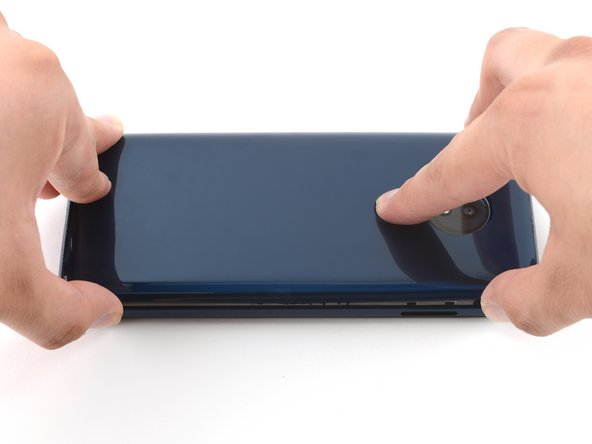
Slightly lift up the rear cover starting from the right side.
-
This will prevent damage to the fingerprint sensor connector under the left side of the rear cover.
-
Use a finger to press down on the fingerprint sensor until it separates from the rear cover.
I had to cut some of the adhesive on the left side of the phone also. Fortunately, there is nothing sensitive close to the edge and everything is covered with a shield.
-
-
-
Remove the rear cover, taking care not to damage the fingerprint sensor.
-
-
-
-
Insert the pointed end of a spudger into the divot at the top of the fingerprint sensor connector cover.
-
Gently pry the cover open.
-
Remove the cover.
-
-
-
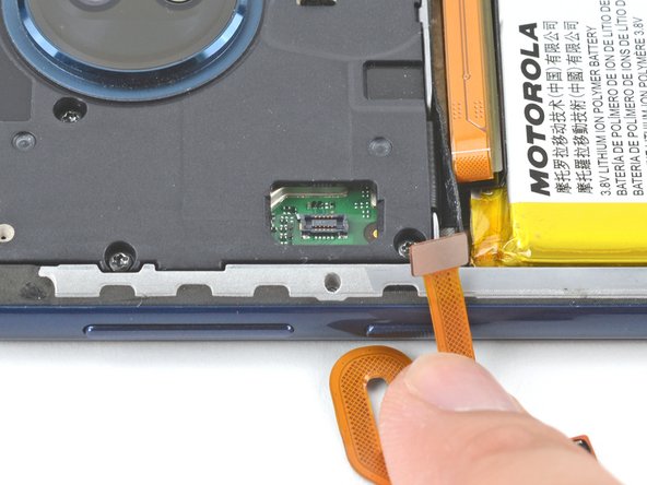
Use the pointed end of a spudger to pry up on the fingerprint sensor connector to disconnect it.
-
-
-
Use a T5 Torx screwdriver to remove the ten screws securing the motherboard cover to the midframe:
-
Nine 3.5 mm screws
-
One 3.0 mm screw
On my phone the 3.0 mm screw was on the top-middle-right. It is covered with a tamper seal.
On my phone the middle screw on the right was covered, but all of the screws seemed to be exactly the same size.
I looked very carefully at all the screws, lining them up next to one another, and could not spot one that was shorter than the others.
-
-
-
Insert the flat end of a spudger under the motherboard cover.
-
Pry the motherboard cover upwards to lift it from the motherboard.
-
Remove the motherboard cover.
-
-
-
Use the flat end of a spudger to pry up on the battery connector to disconnect it.
-
-
-
Use a T5 Torx screwdriver to remove the four 2.5 mm screws securing the daughterboard cover to the midframe.
-
-
-
Insert the flat end of a spudger under the daughterboard cover and pry upwards.
-
Remove the daughterboard cover.
-
-
-
Slide one of the tweezer's tips under the black wire until it's snug against the connector, and pry straight up from the board.
My phone had the white wire on top of the black one, so I reversed these two steps. It’s recommended that the top wire is removed first, regardless of its color.
-
-
-
Slide one of the tweezer's tips under the white wire until it's snug against the connector, and pry straight up from the board.
-
-
-
Use the flat end of a spudger to pry up on the interconnect cable connector to disconnect it.
-
-
-
Use a T5 Torx screwdriver to remove the 3 mm screw securing the daughterboard to the midframe.
-
-
-
Insert the pointed end of a spudger under the right side of the daughterboard to lift it from the midframe.
-
Remove the daughterboard.
-


To reassemble your device, follow these instructions in reverse order.
Take your e-waste to an R2 or e-Stewards certified recycler.
Repair didn’t go as planned? Try some basic troubleshooting, or ask our Motorola Moto G7 Power Answers community for help.
Compare your new replacement part to the original part—you may need to transfer remaining components or remove adhesive backings from the new part before you install it.
crwdns2935221:0crwdne2935221:0
crwdns2935229:09crwdne2935229:0

crwdns2947412:05crwdne2947412:0
IMEI is now 0 and I get "this sim is disabled".....
So where can I get this daughterboard? I see no link to buy it up there and can't find it anywhere else, either...
Thanks for a well-done guide - very useful! I also replaced the fingerprint sensor after having broken the cable when installing a new battery last year. Nice to have all the capabilities of the phone again!
I retired my G7 Supra a few years ago. Great extra phone but part of the plastic around the port gave way which led to the charging port getting damaged. I have a use for extra phones and this old girl isn’t a slouch. $11 on Amazon for the part and following this tutorial, I got it done in 30 minutes. Hardest part was the adhesive.
Thanks so much!! It’s now plugged in a turbo charging. I reinforced the plastic around it with two little thin pieces of aluminum and some in weld. Moto definitely had a design flaw there.
I’ll be posting a video to my audience on YouTube (Silly Reviews) and sharing the link to this page.
In my case, I heated the iOpener in boiling water for more than 2 minutes, but this did not weaken the adhesive. With the hair dryer it finally worked.
Elmar - crwdns2934203:0crwdne2934203:0