crwdns2915892:0crwdne2915892:0
This guide will walk you through the process of replacing a faulty headphone jack in a Motorola Moto G4 Plus phone.
Before you begin, download the Software Fix app to backup your device and diagnose whether your problem is software or hardware related.
crwdns2942213:0crwdne2942213:0
-
-
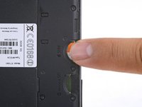
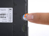
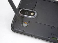
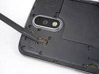
Insert a fingernail or a spudger into the notch on bottom edge of the phone near the charging port.
-
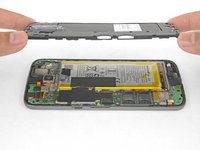
Pry the back cover away from the body of the phone.
-
-
-
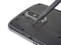
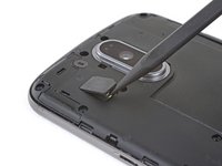
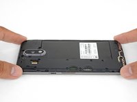
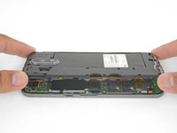
Continue to gently lift the back cover until all plastic clips have been released.
-
Remove the back cover.
-
-
-
Slide out and remove the SIM card.
Tenho un Motorola g4 plus 64 G
El celular se volvía loco abriendo y cerrando aplicaciones
Ahora no reconoce la tarjeta SIM
Internet y Wasapp funciona
Alguien sabe donde lo reparan soy de Argentina Buenos Aires CABA
-
-
-
Remove the nineteen 3.1 mm T3 screws securing the midframe.
A pair of binocular magnifiers is helpful here. Also, a magnetic pickup will help pull the tiny screws out of their counterbores.
Well I'm stuck. 3 screw heads are stripped on mine, not lucky as they are two on USB port end and screw in-between two SIM slots. Phone bought new and this is 1st time screws have been touched, could see they were already stripped before getting screwdriver near them. Any tips on removing stripped screws?
Hi Mark,
I’m sorry to hear that! You can try some techniques from the stripped screw guide.
I found that a T4 driver was the correct size for the screws.
-
-
-
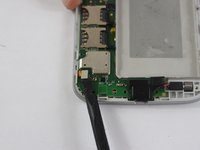
Use the point of a spudger to pry up the rubber cover over the camera flash connector.
-
Remove the rubber cover.
-
-
-
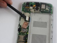
Use the point of a spudger to pry up and disconnect the camera flash connector.
-
-
-
Loosen the midframe along the edges and lift it away from the body.
-
Remove the midframe.
-
-
-
-
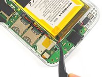
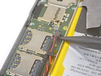
Peel up and remove the tape securing the battery wires.
-
Peel up and remove the black tape that bridges the battery and the phone.
-
-
-
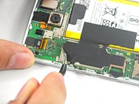
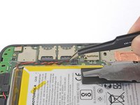
Slip the point of a spudger underneath the red and black battery wires and gently pry straight up.
This one is really difficult. I failed to vertically pull the plug. In the end, the wire ends came out of the plug. Luckily, the openings for the wires give some grip for tweezers to pull the plug upwards.
-
-
crwdns2935267:0crwdne2935267:0Tweezers$4.99
-
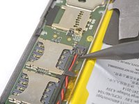
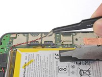
Use tweezers or your fingers to de-route the battery wires from the plastic brackets.
-
-
-
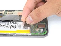
Peel the black pull tab from battery and pull slowly but firmly to separate the battery from the frame.
Does anybody know, what the black tape covering the metal cans an the battey is made of? It seems to have a heat insulating effect.
No, but the tape completely separated from itself when I removed it. Glue separated from the backing. I figure the glue in the frame is holding it well enough.
I found prying the battery out was the trickiest part of this job. Take your time and pry with the plastic tool, working from the end away from the wires, but try not to deform the battery in the process. It does finally come out.
Hi, I cannot remove the Battery, it has too strong glue. Any Ideas?
Regards
You can try to drip some high concentration isopropyl alcohol along the battery edge to help loosen the adhesive.
-
-
crwdns2935267:0crwdne2935267:0Tesa 61395 Tape$5.99
-
Remove the battery.
-
-
crwdns2935267:0crwdne2935267:0Tweezers$4.99
-
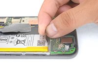
Using tweezers, lift up the black silicon piece connecting the motherboard to the front casing.
-
Using tweezers, remove the red and black cable connecting the motherboard to the front casing.
-
-
-
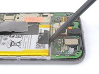
Using a spudger, remove the two metal pieces connecting the motherboard to the front casing.
What is the purpose of that metal piece that is connected to the motherboard on the bottom left-hand side.
Its for the fingerprint scanner (only on the G4 Plus)
-
-
-
Using tweezers, remove the yellow film connecting the rear camera to the motherboard.
-
-
-
Remove two 4.0 mm T3 Torx screws connecting the motherboard to the front casing.
-
-
-
Using a spudger, lift up and remove the motherboard.
-
-
crwdns2935267:0crwdne2935267:0Tweezers$4.99
-
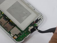
Using tweezers, lift up the black silicon piece covering the audio jack.
-
-
-
Using tweezers, remove the audio jack.
-


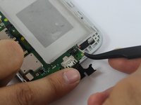


To reassemble your device, follow these instructions in reverse order.
To reassemble your device, follow these instructions in reverse order.
crwdns2935221:0crwdne2935221:0
crwdns2935229:09crwdne2935229:0
crwdns2915084:0crwdne2915084:0

USF Tampa, Team S2-G6, Sullivan Spring 2017 crwdns2935289:0USF Tampa, Team S2-G6, Sullivan Spring 2017crwdne2935289:0
USFT-SULLIVAN-S17S2G6
crwdns2931471:04crwdne2931471:0
crwdns2935297:014crwdne2935297:0
crwdns2947410:01crwdne2947410:0
I accidentally broke the headphone jack ribbon cable socket off of the motherboard - its a very small 3 socket ZIF connector that wasn’t attached very good. Now I have no display - I’m wondering if the headphone jack has something to do with it? I would think breaking that connector would only affect the headphone jack.