crwdns2915892:0crwdne2915892:0
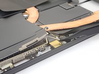
The camera tie bar mounts the front and rear cameras as well as providing additional mounting support for the right and left speakers. It also connects to the motherboard via a small ribbon cable.
crwdns2942213:0crwdne2942213:0
-
-
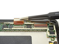
Use a spudger to flip up the small locking flaps on the display cable ZIF connectors.
-
-
crwdns2935267:0crwdne2935267:0Tweezers$4.99
-
Use tweezers to slide the display cables straight out of their sockets on the display board.
-
-
-
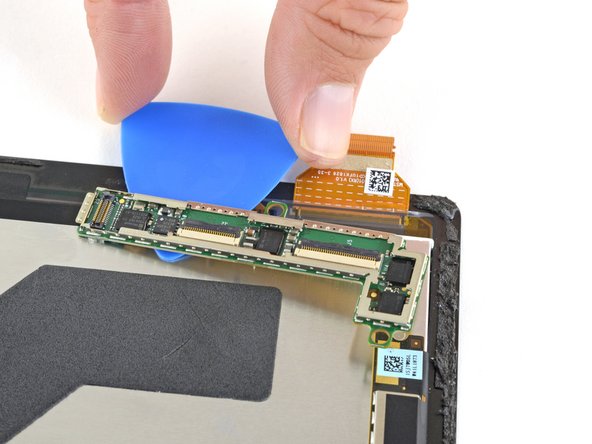
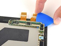
Slide an opening pick under the display board to separate the adhesive holding it onto the back of the screen.
-
-
crwdns2935267:0crwdne2935267:0Tesa 61395 Tape$5.99
-
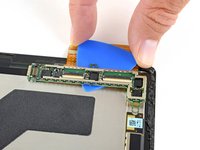
Remove the display board.
-
To ensure correct positioning, plug in both display connectors before adhering the board to the display.
-
-
-
Only the screen remains.
Note, on the flex connectors of the new screen are blue strips of protective plastic covering factory applied conductive adhesive. These must be removed and the adhesive must bond to the display board in order for the touch screen digitizer to function reliably.
-
-
-
crwdns2935267:0crwdne2935267:0Tweezers$4.99
-
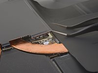
Insert one point of a pair of pointed tweezers into a gap in the corner of the EMI shield covering the heat sink.
-
Use the tweezers to pry the EMI shield away from the motherboard as much as you can without bending it. Do not remove it yet.
Black spudger worked best to get the emu shields out without damaging them.
-
-
-
Repeat the last step for each corner of the EMI shield covering the heat sink.
-
-
-
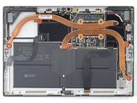
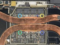
Remove the nine Torx screws securing the heat sink:
-
Five 2.6 mm-long T3 screws
-
Four 3.3 mm-long T5 screws
-
Screw 1
-
Screw 2
-
Screw 3
-
Screw 4
Just like to add, on my i7, there is a fan in the top left corner and the heat sink is glued to the cover. The cover must be removed using a ph0 x 3 and one T3 (I think that is the sizes)
As the other person commented, mine also had a fan connected to the heatsink. This is present in the version with an Intel Core i7-7660U. It requires removing a T3 and T5 screw and the fan connector. Below is a link to an image showing this step.
While I do not have the fan present in my i5 version, the copper heat pipe does extend further down on the far left side (as oriented in the picture). There is an additional T3 screw on this arm as well as a small dab of adhesive on the very end.
My i5 surface pro 5 has 6 of the T3 screws as the heat sink extends slightly further down.
-
-
-
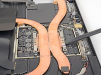
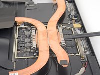
Use the flat end of a spudger to gently pry the heat sink straight up and off of the CPU.
-
-
-
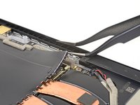
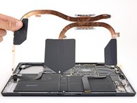
Remove the Torx T5 x 6mm screw connecting the black tie bar to the power button/volume control/speaker assembly.
-
-
-
Remove the remaining three Torx T5 x 4.5mm screws holding down the camera tie bar.
-
-
crwdns2935267:0crwdne2935267:0Tweezers$4.99
-
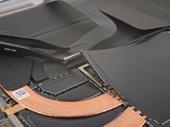
Disconnect the small ribbon cable connecting the camera tie bar to the motherboard by pulling up with tweezers.
-
-
-
Lift the camera tie bar off of the device.
-


To reassemble your device, follow these instructions in reverse order.
To reassemble your device, follow these instructions in reverse order.
crwdns2935221:0crwdne2935221:0
crwdns2935227:0crwdne2935227:0
crwdns2915084:0crwdne2915084:0

Cal Poly, Team S15-G3, Livingston Fall 2017 crwdns2935289:0Cal Poly, Team S15-G3, Livingston Fall 2017crwdne2935289:0
CPSU-LIVINGSTON-F17S15G3
crwdns2931471:03crwdne2931471:0
crwdns2935297:017crwdne2935297:0
crwdns2947412:02crwdne2947412:0
Do you really need to remove the heat sink shield and the heat sink to disconnect the tie bar small ribbon cable ?
round rubber?