crwdns2915892:0crwdne2915892:0
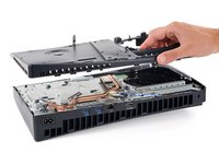
This guide shows how to remove the main board. This is required before replacing the liquid metal.
crwdns2942213:0crwdne2942213:0
-
-
Shut down your console and unplug all cables and accessories.
-
Remove any stands supporting your device and lay it down.
-
-
-
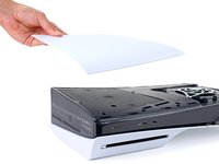
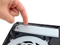
To remove a cover, firmly pull up the front edge to release the clips.
-
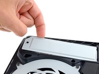
Remove the cover.
-
-
-
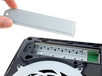
Use the same process to remove the three remaining covers.
-
-
-
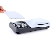
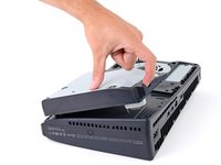
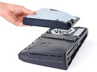
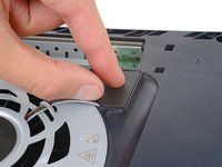
Use the cutout on the bottom right corner of the disc drive to lift its right edge and disconnect it.
-
Remove the disc drive.
-
-
crwdns2935267:0crwdne2935267:0FixMat$36.95
-
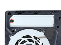
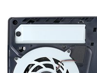
Use a Phillips screwdriver to remove the 17.1 mm‑long screw securing the expansion slot cover.
-
-
-
Use your fingers to lift the expansion slot cover near the notch by the screw hole and remove it.
-
-
crwdns2935267:0crwdne2935267:0Tesa 61395 Tape$5.99
-
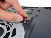
Use your fingers to remove the plastic cover hiding the fan cables connector.
-
-
-
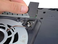
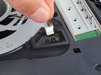
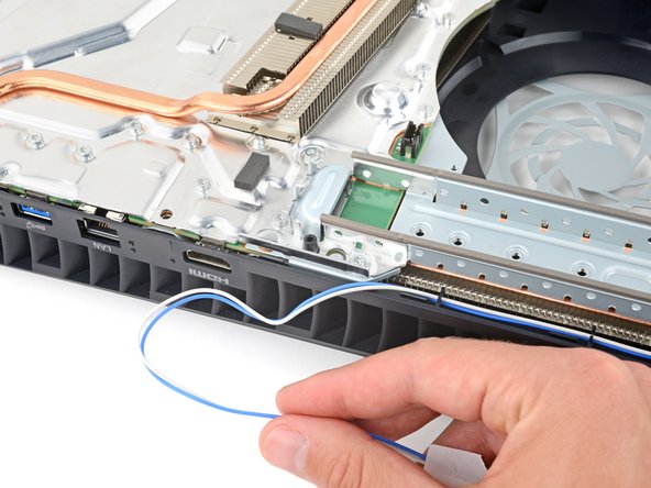
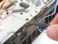
Gently pull the fan cables out from under their plastic clip on the frame.
-
-
-
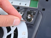
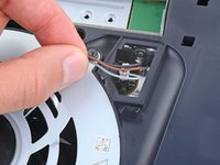
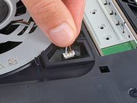
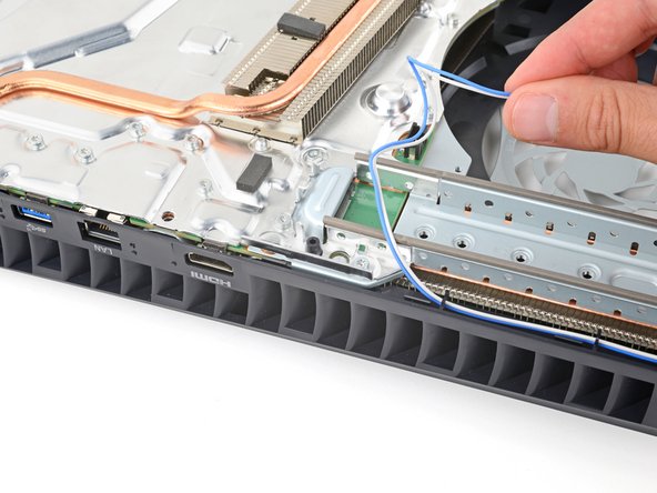
Firmly grip the fan cables white connector head and pull it straight up and out of its socket.
-
-
-
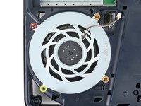
Use a T8 Torx Security screwdriver to remove the four screws securing the fan:
-
One 31.2 mm‑long screw
-
Two 21.3 mm‑long screws
-
One 11.6 mm‑long screw
-
-
-
-
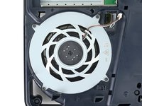
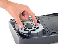
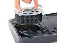
Use your fingers to grab the fan by its vents, and lift it straight up to remove it.
-
Insert the fan so its cables are near their connector.
-
-
crwdns2935267:0crwdne2935267:0Tweezers$4.99
-
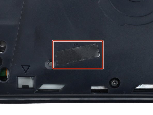
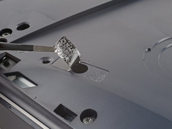
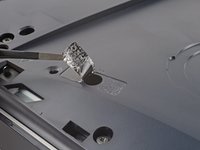
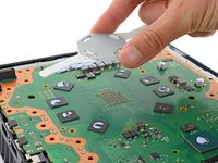
A tamper-evident sticker hides one of the main board cover screws.
-
Use tweezers to peel up the sticker up until you can access the screw underneath.
-
-
-
Use a T8 Torx Security screwdriver to remove the nine screws securing the main board cover:
-
Four 18.9 mm‑long screws
-
One 21.3 mm‑long screw
-
Four 31.2 mm‑long screws
-
-
-
Lift the main board cover straight up and remove it.
-
-
-
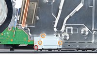
Use a T8 Torx Security screwdriver to remove the four screws securing the interconnect cable cover:
-
One 28.7 mm‑long screw
-
Three 7.5 mm‑long screws
-
-
-
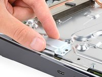
Remove the interconnect cable cover.
-
-
-
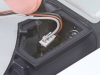
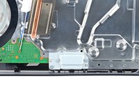
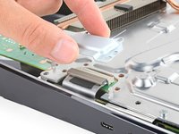
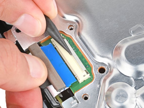
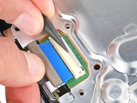
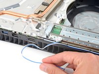
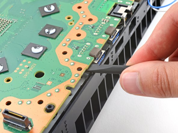
Use the point of a spudger to push the interconnect cable's metal latch down and away from the connector to unlock it.
-
Keep the latch in its unlocked position and carefully pull the interconnect cable straight out of its socket.
-
-
-
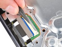
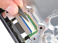
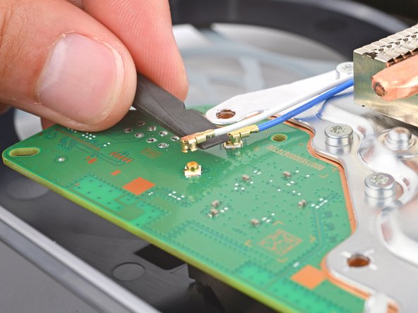
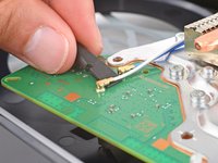
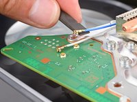
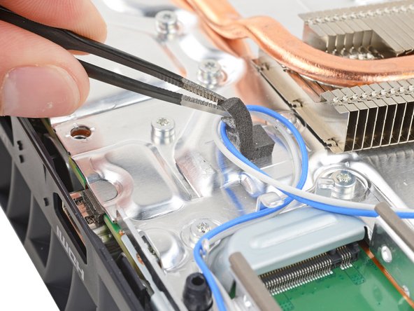
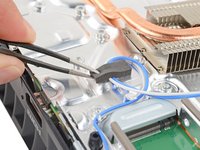
Insert the flat end of a spudger under the metal neck of one of the antenna cable's coaxial connectors and lift straight up to disconnect it.
-
Repeat the process to disconnect the other antenna cable.
-
-
-
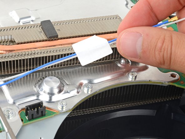
Gently lift both antenna cables to separate the tape from the heatsink shield.
-
-
-
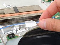
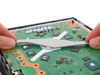
Use tweezers to gently peel up the foam block.
-
-
-
Move the antenna cables over the side of your PlayStation so they're out of the way.
-
-
-
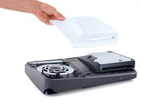
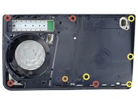
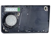
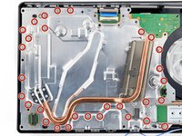
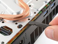
Use a T8 Torx Security screwdriver to remove the thirty 7.5 mm‑long screws securing the top shield plate.
-
-
-
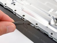
Insert the flat end of a spudger between the top shield plate and the main board and pry up to release the plate. Work your way around the perimeter until it separates completely.
-
-
-
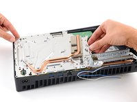
Lift and remove the top shield plate.
-
-
-
Use a T8 Torx Security screwdriver to remove the four remaining screws securing the main board:
-
Two 7.5 mm‑long main board screws
-
Two 16.3 mm‑long screws securing the APU tension bracket
-
-
-
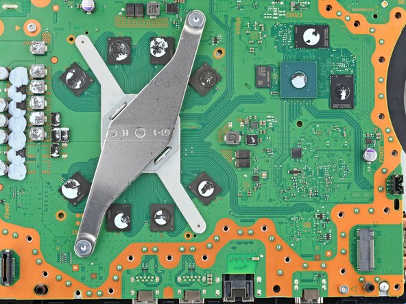
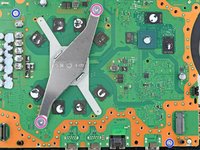
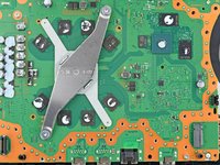
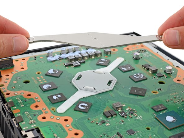
Lift and remove both APU brackets from the board.
-
Put the bracket with plastic arms on first so the pegs go into their cutouts.
-
Then, put the metal bracket onto the plastic one so they're perpendicular and the screw holes line up.
-
-
-
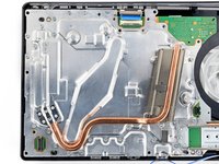
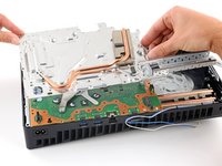
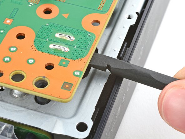
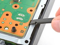
Gently lift the edge of the motherboard with the large cutout to partially separate it from the bottom shield plate.
-
With the board lifted, insert the flat end of a spudger between the board and the bottom shield plate and gently twist to separate them. Work your way around the perimeter of the board.
-
-
-
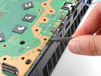
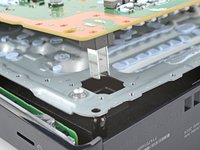
Insert the flat end of a spudger between the board and the lower shield plate, by the two parallel solder joints near the corner with the power button.
-
Use your spudger to pry up the board until the two prongs come completely out of their socket.
-
-
-
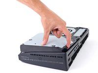
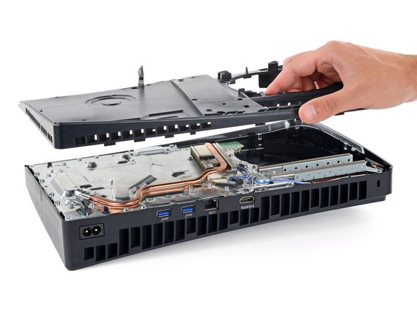
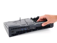
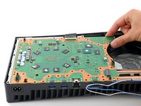
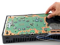
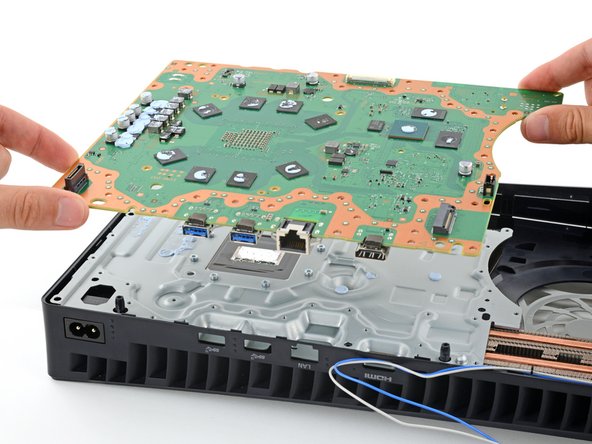
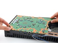
Remove the main board, flip it over, and carefully lay it on a clean work surface, so the APU is facing up.
-
Make sure all cables that connect to the board are out of the way so they don't get trapped underneath.
-
Carefully flip the board over so the APU is on the bottom, making sure no liquid metal spills.
-
Keep the board level and lower it into place.
-


To reassemble your device, follow these instructions in reverse order.
To reassemble your device, follow these instructions in reverse order.

