crwdns2915892:0crwdne2915892:0
The ins and outs of replacing your upper case.
crwdns2942213:0crwdne2942213:0
-
-
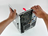
With the case closed, place the Unibody top-side down on a flat surface.
-
Depress the grooved side of the access door release latch enough to grab the free end. Lift the release latch until it is vertical.
-
-
-
The access door should now be raised enough to lift it up and out of the Unibody.
-
-
-
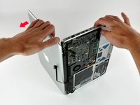
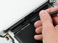
Grab the white plastic tab and pull the battery up and out of the Unibody.
Great tutorial ! great step !
Even though it’s specifically stated, you have to make sure the access door latch is vertical or the battery won’t be removable.
-
-
-
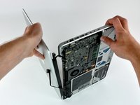
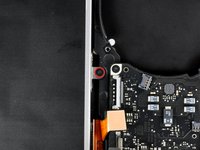
Remove the following eight screws securing the lower case to the chassis:
-
One 3 mm Phillips screw.
-
Three 13.5 mm Phillips screws.
-
Four 3.5 mm Phillips screws.
On my model, it seemed the top-left was 3.5mm and the bottom 4 were 3 mm.
Make sure you have a good quality Phillips screwdriver. Mine had removable tips and had a small play at the connection. As a result I didn't have a good feel and damaged my screws (those securing the fan and the top left in step 23). Game over for me installing new thermal paste...
Be very carefull with your screws! Especially those on the inside.
You can get away with a Phillips #00 for many of the screws involved but the 4 at the bottom case split are likely to strip if you don’t use a JIS #00 or, in a pinch, a Phillips #000.
I used the Phillips #00 tip from my Pro Tech Toolkit, and it worked well enough. But yes, maybe #000 might have been better on the lower row of screws. Note to myself: Always read the comments first.
When replacing these screws, the order to replace them in is as follows:
1, Top left
2. Top right
3. Top center-left
4. Top center-right
5. Bottom center-right
6. Bottom center-left
7. Bottom right
8. Bottom left
I hope this information is helpful.
I followed my usual process of putting in all the screws loosely, then tightening them gradually in distributed pattern, to help ensure that the panel settles in place evenly. But maybe some orders are better.
-
-
-
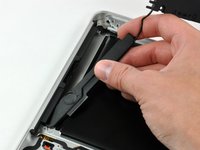
Using both hands, lift and remove the lower case off the upper case.
Thanks for the guide!
It's implicit in the two photos, but worth mentioning because it blocked my progress in this step for a bit: You have to put the release latch back into its horizontal, closed position before you can lift off the lower-case panel.
-
-
-
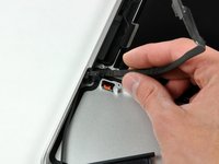
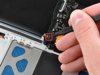
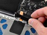
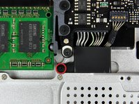
Disconnect the camera cable by pulling the male end straight away from its socket.
Be EXTREMELY careful when removing and re-inserting the 'camera' cable. The contacts can be easily bent beyond repair if you try to force it back in. Damaging this cable at this connection or near the display may disable your ability to use your iSight camera, AND both your Bluetooth and WiFi. I had to pay apple $300 to replace the entire display assembly because one prong was faulty, causing my WiFi card to not be recognized.
-
-
-
De-route the camera data cable from the channel in the optical drive.
Although I ordered the screen for an A1278 MacBook Unibody Aluminum, the screen glass was marked as a MacBook Pro. The iSight/WiFi /BT cable was about an inch longer than the Macbook one and took a bit of creative re-routing, but everything works fine.
has it got the airport and bluetooth modules built in separately in the display assembly as in the macbook late 2008 and mbp mid 2009?
fericcio -
-
-
-
Remove the following screws securing the camera data cable and right speaker to the upper case:
-
One 9.9 mm partially threaded Phillips screw
-
One 9.6 mm threaded Phillips screw
-
One 4 mm Phillips screw
-
Slide the camera cable bracket out from under the subwoofer and remove it from the computer.
"orange" is the short one, that goes in the middle ;)
My model has different bracket, you need to remove the subwoofer first
1. With my Laptop, the left screw was partially threaded, not the right one. 2. Before removing the camera cable bracket, I needed to unscrew the subwoofer.
-
-
-
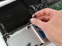
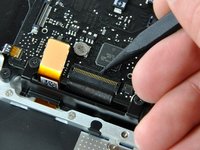
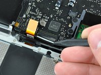
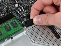
Grab the plastic pull tab secured to the display data cable lock and rotate it toward the DC-in side of the computer.
-
Pull the display data cable connector straight away from its socket.
i can't understand what I need to do in this step, I'm afraid with this step, i think i can "hurt" my mac and i don't want to do that, anyone knows what i need to do?
Thanks
There is a steel 'latch' that flips over from the left side of the connector, to the right side. After you flip this latch over, the cable will easily slide out.
as I pulled the monitor cable out of the bracket after flipping the lock over one side of the bracket broke loose. Now the monitor will not turn on. Can anyone help?
-
-
-
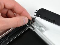
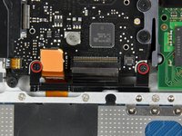
Remove the following two screws from the display data cable bracket:
-
One 7 mm Phillips screw.
-
One 5 mm Phillips screw.
-
Lift the display data cable bracket out of the upper case.
Note for Step 10 during reassembly: Be careful when replacing the screw for the display cable bracket closest to the magnetic power cord receptacle. The interior magnet might attract the screw causing the screw to get pulled under the DC power circuit board which might then require that you disassemble things again to retrieve the screw.
-
-
-
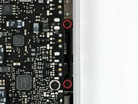
Remove the two outer 6 mm Torx screws securing each side of the display to the upper case (4 screws total).
Hey guys, with these older models Do Not interchange different colored LVDS cables. Note the connector here is gold, do not use a silver connector on a gold one or vice versa. I fried a logic board this way on an A1278. Note that the core i7 lvds connector is different than the core i5.
I never thought that I’d be required to use PB Blaster to remove computer screws. Had to use two tiny drops for each screw, letting it soak in for 20 minutes or so. The display screws, coated with blue thread lock, did not want to budge. I was so fearful that I would strip them using a T-6 driver. Ended up using a 1/4” drive ratchet with a T-6 bit, pressing down firmly and blocking the MacBook from turning with my elbows. I’ve had a lot of experience doing this kind of work, but wow!
-
-
-
Open your MacBook so the display is perpendicular to the upper case.
-
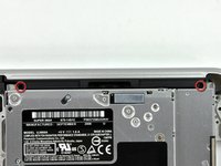
Place your opened MacBook on a table as pictured.
-
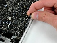
While holding the display and upper case together with your left hand, remove the 6 mm Torx screw from the lower display bracket.
-
-
-
Remove the last remaining 6 mm Torx screw securing the display to the upper case.
-
-
-
Grab the upper case with your right hand and rotate it slightly toward the top of the display so the upper display bracket clears the edge of the upper case.
-
Rotate the display slightly away from the upper case.
-
Lift the display away from the upper case, minding any brackets or cables that may get caught.
-
-
is it still possible to have a backlight keyboard, even if theres no socket installed?
I would like to know as well. Can a socket be soldered to the board in this spot?
I dont think so coz if apple havent soldered necessary driver chip and circuit for backlight, there is no need to solder that socket. That chip has to be on other side of the board
Oleg R -
Yes I believe it can as that is just power for the backlight I believe.... but I have never done this mod to a macbook without the socket.
The socket for the backlight was snap off when I was removing the ribbon cable. Does anyone know where can I get a replacement for the socket?
If you have the skill to solder a new connector on, the best option would probably be to look for a donor motherboard.
Bagel -
-
-
-
Remove the single Phillips screw securing the hard drive bracket to the chassis.
-
-
-
Lift the hard drive by its pull tab enough to grab and remove the retaining bracket.
-
Lift the hard drive out of the chassis, minding the cable attaching it to the computer.
-
-
-
Remove the hard drive from its cable by pulling the cable connector straight away from the drive.
-
-
-
Remove the four 10.3 mm Phillips screws securing the mid wall to the upper case.
Need to add a step above this to remove the bottom cover.
-
-
-
Lift the mid wall out of the upper case.
-
-
-
Remove the following three screws securing the fan to the upper case:
-
Two 5 mm Phillips screws.
-
One 7 mm Phillips screw.
-
-
-
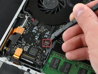
Use a spudger to pry the fan connector straight up and out of its socket on the logic board.
-
-
-
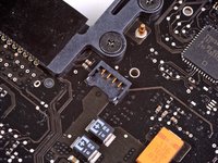
Using the flat end of a spudger, pry the subwoofer connector straight up off the logic board.
-
-
-
Remove the single Phillips screw securing the subwoofer to the upper case.
-
-
-
Lift the subwoofer off the optical drive, and set it above the computer.
-
-
-
Use a spudger to pry the optical drive connector straight up off the logic board.
-
-
-
Use the flat end of a spudger to pry the hard drive cable connector straight up off the logic board.
-
-
-
Remove the three 2.5 mm Phillips screws securing the optical drive to the upper case.
-
-
-
Lift the optical drive from its right edge and pull it out of the computer.
-
-
-
Peel the hard drive cable from the adhesive securing it to the upper case, and maneuver the plastic retaining block out of the upper case.
-
-
-
Peel back the small piece of black tape covering the right speaker cable.
-
Use the tip of a spudger to pry the right speaker up off the adhesive securing it to the upper case.
-
Lift the subwoofer and right speaker assembly out of the upper case.
I left it in place. It was not necessary to remove it for replacement of the keyboard.
-
-
-
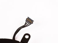
Use the tip of a spudger to flip up the locking lever to release the IR sensor ribbon cable from its socket.
-
Pull the IR sensor ribbon cable straight away from the logic board.
Pull the IR sensor ribbon cable straight away from the logic board.
Could be useful with a comma
-
-
-
Use the flat end of a spudger to pry the trackpad connector straight up off the logic board.
-
-
-
Using the tip of a spudger, flip up the keyboard ribbon cable retaining flap.
-
Pull the keyboard ribbon cable straight out of its socket.
When you are on the way back, this is where you can connect the keyboard lighting. You put the flat cable from the new keyboard into the connector directly to the right of the one for the keyboard ribbon cable. It shows itself!
-
-
-
Remove the two 5 mm Phillips screws securing the keyboard flex bracket to the upper case.
-
Lift the keyboard flex bracket out of the upper case.
-
-
-
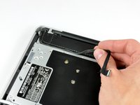
Remove the single Phillips screw securing the battery cable cover to the upper case.
-
Remove the battery cable cover from the upper case.
-
-
-
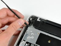
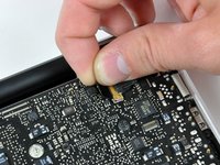
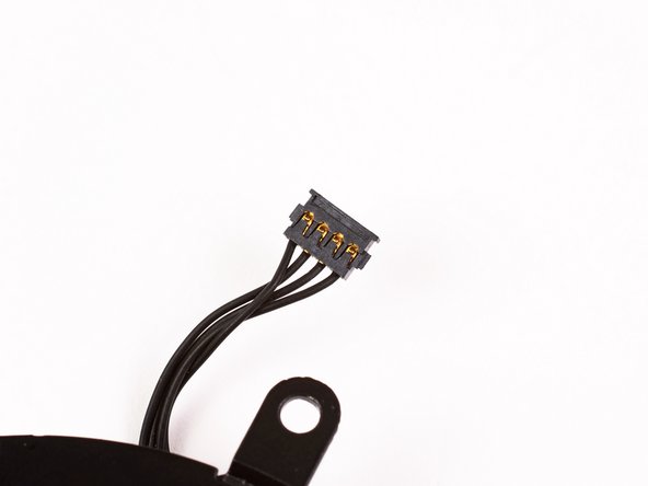
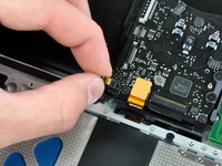
Use a spudger to pry the battery level indicator cable connector straight up off the logic board.
-
-
crwdns2935267:0crwdne2935267:0Tweezers$4.99
-
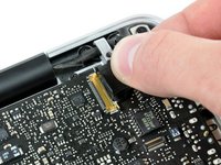
Disconnect the battery cable connector by pulling it straight away from the logic board.
-
-
-
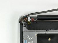
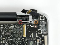
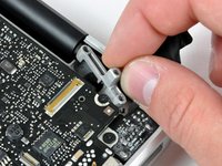
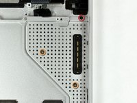
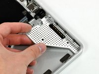
Remove the two 4mm Phillips screws securing the bottom case clip to the upper case.
-
Lift the bottom case clip out of the upper case.
I didn't have that part in my MB at all
Yup me either
AOL. E..g. mine was lacking this part (and its mounting holes) too.
I think this is the wrong photo. The part you have to remove is a bridge above the microphone.
-
-
-
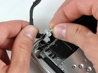
Use the tip of a spudger to release the microphone from the upper case.
It might be worth noting the microphone is glued to the Upper Case.
-
-
-
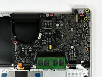
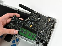
Remove the following five screws securing the logic board to the upper case:
-
Four 3 mm Phillips screws.
-
One 3.5 mm Phillips screw.
-
Remove the two 7 mm Phillips screws securing the DC-in board to the upper case.
-
Lift the logic board from its left edge and pull it out of the upper case.
Note to Step 41: the 3.5 mm Phillips screw and the 3 mm Phillips screw directly opposite were swapped in my MacBook. I believe the screws as indicated in the iFixIt guide are currently incorrect as it seems that the location in my MacBook would be correct as all 3 mm screws engage directly into the top case while the one 3.5 mm screw engages into the black bracket.
With my MacBook, the left screw (near the fan) was 5mm (not 3), the other “red” screws were 3mm (as indicated) and the “orange” one was 3.8mm (not 3.5).
-
-
-
Remove the following screws securing the battery connector cover to the upper case:
-
One 2.5 mm Phillips screw.
-
Two 1.5 mm Phillips screws.
-
Lift the battery connector cover out of the upper case.
-
-
-
De-route the battery connector cable through the gap in the upper case and remove it from the computer.
During your checkout of your hard work, make sure in System Preferences that the (use all F1, F2 etc. keys as standard function keys) box is unchecked.
It was not necessary to remove this item for me. I could remove the keyboard with it in place
-


To reassemble your device, follow these instructions in reverse order.
To reassemble your device, follow these instructions in reverse order.
crwdns2935221:0crwdne2935221:0
crwdns2935229:026crwdne2935229:0

crwdns2947410:01crwdne2947410:0
Having difficulty putting that keyboard ribbon cable back in?
MacBook unibody keyboard ribbon cable won't go in
Put some scotch tape on it and pull up and in.
This is not a a1278 unibody MacBook Pro. A1278 MacBooks backs are one solid metal piece not two separate pieces. This guide is for a different MacBook Pro.
Brad Burgeson - crwdns2934203:0crwdne2934203:0
This guide isn’t for a pro; it’s a MacBook unibody.
Nicholas -
So, it turns out that Apple used the model code A1278 for quite a few different Mac models, including both Pro and non-Pro versions! This guide is for the non-Pro Macbooks. There’s also one for the Pro models with the same A1278 identifier.
tempelmann - crwdns2934203:0crwdne2934203:0