crwdns2942213:0crwdne2942213:0
-
-
Remove the following ten screws:
-
Three 14.4 mm Phillips #00 screws
-
Three 3.5 mm Phillips #00 screws
-
Four 3.5 mm shouldered Phillips #00 screws
-
-
-
Use your fingers to pry the lower case away from the body of the MacBook near the vent.
-
Remove the lower case.
-
-
-
Use the edge of a spudger to pry the battery connector upwards from its socket on the logic board.
-
-
-
Bend the battery cable slightly away from its socket on the logic board so it does not accidentally connect itself while you work.
-
-
-
Use the flat end of a spudger to pry the AirPort/Bluetooth ribbon cable connector up from its socket on the logic board.
-
-
-
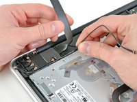
Carefully pull the camera cable out of its socket on the logic board.
-
-
-
-
Carefully move the AirPort/Bluetooth ribbon cable out of the way as you peel the camera cable off the adhesive securing it to the subwoofer and the AirPort/Bluetooth bracket.
-
De-route the camera cable out from under the retaining finger molded into the AirPort/Bluetooth bracket.
-
-
-
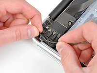
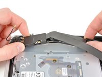
Use the tip of a spudger to pry the antenna connector closest to the logic board up from its socket on the AirPort/Bluetooth board.
-
De-route the antenna cable from under the finger molded into the AirPort/Bluetooth bracket.
-
-
-
Use a Phillips #00 screwdriver to remove the following five screws:
-
Two 10.3 mm screws
-
Two 3.1 mm screws
-
One 5 mm screw
-
-
-
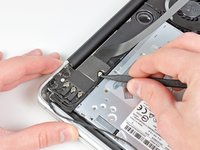
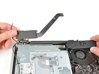
Pull the AirPort/Bluetooth assembly and the Subwoofer upward near the center of the side of the optical drive until they clear each other.
-
Move the AirPort/Bluetooth assembly and the subwoofer away from the top of the optical drive.
-
-
-
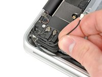
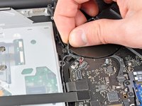
Pull the right speaker/subwoofer cable out from under the retaining finger near the side of the optical drive.
-
Pull the right speaker/subwoofer cable upward to disconnect it from the logic board.
-
-
-
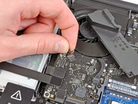
Use the flat end of a spudger to pry the hard drive cable connector up from its socket on the logic board.
-
Bend the hard drive cable away from the optical drive.
-
-
-
Use the flat end of a spudger to pry the optical drive connector up from its socket on the logic board.
-
-
-
Remove the three 2.7 mm Phillips screws securing the optical drive to the upper case.
-
-
-
Pull the optical drive upward from its edge closest to the display and remove it from the upper case.
-
-
-
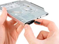
Pull the optical drive cable away from the optical drive.
-
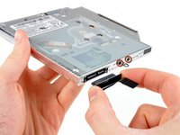
Remove the two black Phillips #0 screws securing the small metal mounting bracket. Transfer this bracket to your new optical drive or hard drive enclosure.
-


To reassemble your device, follow these instructions in reverse order.
crwdns2935221:0crwdne2935221:0
crwdns2935229:0144crwdne2935229:0

crwdns2947412:06crwdne2947412:0
Andrew,
Thank you for this guide. My drive was refusing to write discs, after open it, I found the lens was dirty, nothing a Q-tip and isopropyl alcohol couldn’t clean.
Javier Cano
is it posible to just remove the drive and leave the space empty?
Sure, that will not cause any problems per se.
The perfect guide for taking out an optical drive.
Does the 2009 unibody use the same SATA optical drive as the mid 2012? I have a failed 13" 2012 drive and an early unibody 13" and am wondering if the same drive can be moved over.