crwdns2915892:0crwdne2915892:0
This guide will take you through the steps of replacing the heatsink in your 2018/2019 (A1989)MacBook Pro.
crwdns2942213:0crwdne2942213:0
-
-
Power on your Mac and launch Terminal.
-
Copy and paste the following command (or type it exactly) into Terminal:
-
'sudo nvram AutoBoot=%00
-
Press [return]. If prompted, enter your administrator password and press [return] again. Note: Your return key may also be labeled ⏎ or "enter."
-
sudo nvram AutoBoot=%03
-
-
-
Use a P5 Pentalobe driver to remove the six screws securing the lower case:
-
Two 6.2 mm screws
-
Four 3.4 mm screws
-
-
-
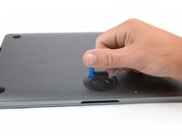
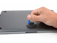
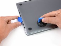
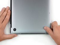
Apply a suction handle to the lower case near the front-center area of the MacBook Pro.
-
Lift the suction handle to create a slight gap between the lower case and the chassis.
-
-
-
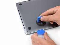
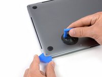
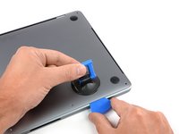
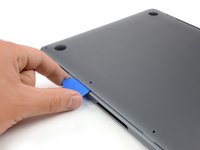
Insert one corner of an opening pick into the space between the lower case and the chassis.
-
Slide the opening pick around the nearest corner and halfway up the side of the case.
-
-
-
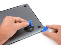
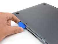
Repeat the previous step on the opposite side, sliding your opening pick under the lower case and up the side to pop the second clip free.
-
-
-
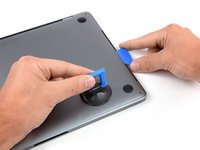
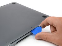
Insert your opening pick once again under the front edge of the lower case, near one of the two centermost screw holes.
-
Give the pick a firm twist to pop free the third clip securing the lower case to the chassis.
-
Repeat this procedure near the other of the two centermost screw holes, popping the fourth clip free.
-
-
-
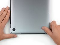
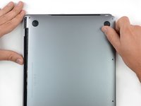
Pull the lower case firmly towards the front of the MacBook (away from the hinge area) to separate the last of the clips securing the lower case.
-
Pull first at one corner, then the other.
-
-
-
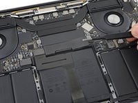
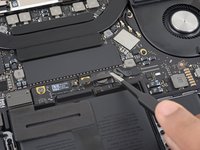
Remove the lower case.
Why does this show a logic board with 2 fans? Mine has only 1 fan.
If yours only has one it’s the 2 thunderbolt model from another year or a MacBook Air of some sort:-)
-
-
-
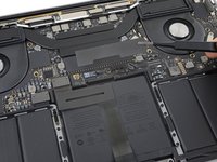
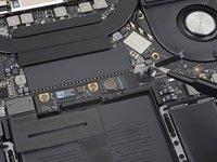
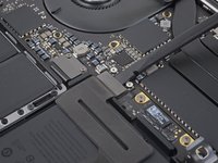
Carefully peel up the large piece of tape covering the battery connector, on the edge of the logic board nearest the battery.
-
Remove the tape.
-
-
-
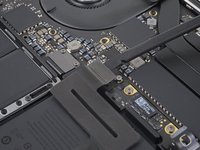
Gently peel back the small piece of tape covering the battery board data cable connector.
-
-
-
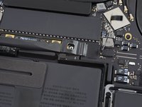
Disconnect the battery board data cable by sliding it out from its socket.
-
Slide parallel to the logic board, in the direction of the cable.
Would be nice to mention the fact you have to lift up the tiny little plastic cable locking device before pulling this ribbon cable out.
-
-
-
Fold the battery board data cable to the side and out of the way.
-
-
-
-
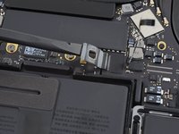
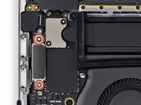
Use a T5 Torx driver to remove the 3.7 mm pancake screw securing the battery power connector.
-
-
-
Use a spudger to gently lift the battery power connector, disconnecting the battery.
-
Lift the connector high enough so that it stays separated from its socket. If it accidentally makes contact during the course of your repair, it could damage your MacBook Pro.
-
-
-
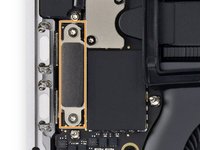
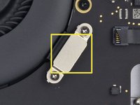
Use a T3 Torx driver to remove the two 1.8 mm screws securing the trackpad cable connector bracket.
use a t4 for and push down hard the screw on the right, it feels like apple just fcks with us for no reason other than to make it harder to fix these things
Correct, T3 did not fit - had to use T4
T5 in MacBook Pro 2019 Touch Bar
-
-
crwdns2935267:0crwdne2935267:0Tweezers$4.99
-
Remove the trackpad cable connector bracket with a pair of tweezers.
-
-
-
Use a spudger to disconnect the trackpad ribbon cable by gently prying its connector straight up from the logic board.
-
-
-
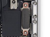
Use a T3 Torx driver to remove the two screws.
-
Two T3 Torx Screws.
These are T3 on this machine I'm working on
Thanks for letting me know:-)
on the machine I was working on I was able to use a T4
But thanks again for letting me know
t3 on left and t4 on right
no shield or screws on my machine, just tape and a zif connector to flip up and disconnect
-
-
-
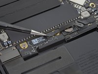
Carefully peel back the black tape to reveal the ZIF connector.
-
Unlatch the ZIF connector by flicking the arm on the connector upwards and carefully remove the cable from the connector by sliding it out.
-
Repeat this process with the newly revealed connector.
the bottom one is very very difficult good luck
make sure you click the piece up before moving the connector ribbons. you will hear a click.
-
-
-
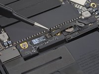
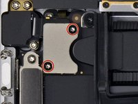
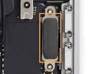
Use a T3 Torx driver to remove the two screws.
-
Once the screw have been removed carefully remove the metal shield.
-
Under the metal shield there is a connector, carefully unplug it.
T3s on my A1989 here.
Thanks for letting my me know:-)
Il change the size
When I was taking my one apart I was able to use a T4
Thanks for letting me know:-)
sometimes t5 needed. ive used t3 and t4 and just before drilling another hole on a whim tried t5
you are missing a picture of the connecter being unplugged (last step on this) step 20
T3 on my emc3214
-
-
-
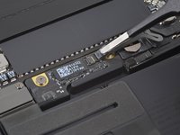
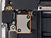
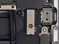
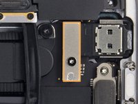
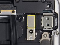
Use a T4 Torx driver to remove the two screws.
-
Two T4 Torx screws.
-
Carefully remove the metal shield.
-
The second cable you will disconnect will be lightly adhered so carefully slide a plastic spudger under it and finally unplug it.
Bear in mind Touch ID is paired to the logic board so if you're replacing the Touch ID along with the logic board, be sure to check the power Touch ID button is mounted correctly and can be depressed before you put the logic board back in. Otherwise you may find yourself taking the board back out again. Don't ask me how I know.
can we get pictures of the two connectors under the shield
The screws on mine appeared to be T3, not T4.
T3 on my emc3214 as well
-
-
-
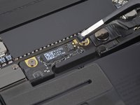
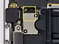
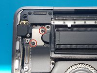
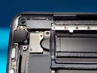
Use a T3 Torx driver to remove the four screws.
-
4 T3 Torx screws.
-
Once the screws are removed carefully remove the metal shields.
-
Carefully unclip the connector.
Bei mir waren die beiden unteren markierten Schrauben nur mit einem Torx T4 lösbar. Außerdem sind sie länger als die oberen Schrauben, was beim Zusammenbau zu beachten war.
upper silver had T4 and thin black clip had T3 screws
-
-
-
Disconnect the cables carefully with a plastic pry tool.
-
-
-
Use a T3 Torx driver to remove the two screws.
-
Remove the metal shield carefully.
-
Carefully unplug the connector.
So where is the touchbar connector on the actual 13 inch Macbook Pro logic board?
Mine is the A2159. This logic is not the one that mine is.
-
-
-
Carefully peel back the black tape to reveal the ZIF connector.
-
Unlatch the ZIF connector by flicking the arm on the connector upwards and carefully remove the cable from the connector by sliding it out.
-
Repeat this process with the newly revealed connector.
-
-
-
Carefully peel back the black tape to reveal the ZIF connector.
-
Unlatch the ZIF connector by flicking the arm on the connector upwards and carefully remove the cable from the connector by sliding it out.
-
-
-
Use a T3 Torx driver to remove the two screws.
-
Once the screw have been removed carefully remove the metal shield.
-
Under the metal shield there is a connector, carefully unplug it.
-
-
-
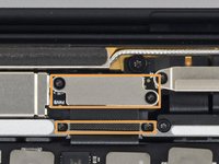
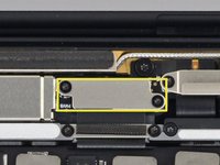
Use a T4 Torx driver to remove the screw.
-
T4 Torx screw.
-
Remove the metal shield carefully.
-
Carefully unplug the connector.
The screw on mine appeared to be T3, not T4.
T3 screw on mine too. 1.8mm i suspect author had odd drivers
-
-
-
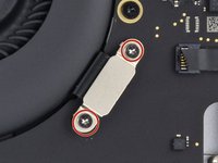
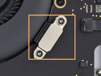
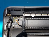
Use a T3 Torx driver to remove the two 1.4mm screws securing the bracket.
-
-
-
gently disconnect the audio socket flex cable with a spudger.
-
gently disconnect the Touch ID flex cable with a spudger.
-
-
-
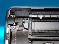
Use a T3 Torx driver to remove the two 2.4mm screws securing the display cable bracket.
-
Use a T3 Torx driver to remove the two 1.2mm screws securing the display cable bracket.
-
-
-
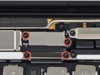
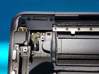
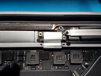
Use a T5 Torx driver to remove the six 2.2mm screws securing the logic board.
-
Use a T3 Torx driver to remove the three 1.9mm screws securing the logic board.
-
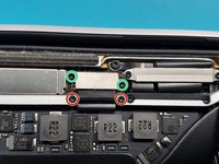
Use a T5 Torx driver to remove the two 2.3mm (3.7mm head) screws securing the heatsink.
The screw under the WiFi / Bluetooth antenna cables is slightly longer than the others circled in red, at least in mine. It makes sense as that location has the additional thickness of the metal shield piece that goes between the screw and the hole.
-
-
-
Congratulations you have now removed your MacBook's LogicBoard
You are actually removing the coolers as well, not only the main logic board.
-
-
-
Use a T5 Torx driver to remove the four 3.2mm screws securing the two heatsink brackets.
-


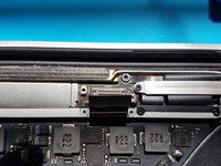


To reassemble your device, follow these instructions in reverse order.
To reassemble your device, follow these instructions in reverse order.
crwdns2935221:0crwdne2935221:0
crwdns2935229:02crwdne2935229:0

crwdns2915084:0crwdne2915084:0

Pickle IT - Gadget Repair crwdns2935289:0Pickle IT - Gadget Repaircrwdne2935289:0
Business
crwdns2931471:02crwdne2931471:0
crwdns2935297:019crwdne2935297:0
crwdns2947412:03crwdne2947412:0
How much replacement thermal paste should be used on the CPU and heatsink?
I cleaned the old dried out thermal paste from the CPU and heatsink and replaced it with a rice grain sized amount of thermal paste, MX-4 on each die. After re-assembly, 2018 Macbook Pro 13" (A1989) works fine but has slightly higher temps and reaches max temps quicker (95C-100C), though idle temps seem lower (35 C). Web browsing is around 57C-60C. The fan also comes on sooner and stays on for longer.
I confirmed the screws holding the clips onto the board and heatsink are fully seated and not cross threaded. The exhaust air seems to be as hot as before, maybe a tiny bit less, so I don't think the heatsink is leaking. I didnt see any liquid on the motherboard.
Should I have used more thermal paste to cover the die AND the CPU package under the heat spreader like pictured in the last step (step 36)?
The only other thing I can think of is the fan duct gaskets are not properly seated and negatively affecting heatsink pressure on CPU dies.
I believe I solved this. I forgot to put the rubber gaskets on the heatsink near the fans. I tried to put them back in after the motherboard and heatsink was already installed. Trying to jam them in must have lifted the heatsink my <1mm causing poor contact.
I was seeing temps up to 100 C and sudden jumps in CPU temperature by 5 or more degree in under 5 seconds.
You can montor CPU temperature with the following command in terminal
sudo powermetrics --samplers smc | ts | grep -i "CPU die temperature"
Ctrl + C to exit
Removed the rubber gaskets for now. Temps dropped down to 50's C with minimal activity, mid 30s during idle and no longer seeing jump in CPU temperature when watching a youtube video. Peaks under full load around 83 C
Will re-install rubber gaskets properly at a later date.
sriag -
Rubber gaskets are pretty important. They form a seal between the bottom case and heatsink/fan. They force air to touch a section of the bottom case and then through the heatsink providing two methods of cooling. Without the rubber gaskets, the hot air circulates through the bottom case which gets hot and barely through the heatsink.
With the gaskets installed properly, temps stay lower longer, when fans are on it temperature drops faster and entire bottom case doesnt get as hot. Hot air is felt exhausting near the display hinges on the back.
Pro tip: install the heatsink rubber gasket seals on the heatsink after securing to the CPU and before reinstalling the motherboard into the case. Make sure they slot properly into the black channels when seating the motherboard into the top case.. while making sure the many cables dont get trapped beneath.
Good luck!
sriag -