crwdns2915892:0crwdne2915892:0
Screen have no backlight? Replace the inverter.
crwdns2942213:0crwdne2942213:0
-
-
Use a coin or spudger to rotate the battery-locking screw 90 degrees clockwise.
 crwdns2952109:0crwdne2952109:0
-
-
-
Lift the battery out of the computer.
-
-
-
Unscrew the three evenly-spaced Phillips 000 screws from along the rear wall of the battery compartment.
-
-
-
Grasp the right end of the L-shaped memory cover, then pull it towards you so it clears the battery compartment opening.
-
Lift the memory cover up and out of the computer.
-
-
-
Remove the following 3 screws:
-
One 11 mm Phillips#00 in the middle of the lower case. (Head: 5mm dia. x .75mm thick)
-
Two 14.5 mm Phillips #00 (Head: 5mm dia. x .75mm thick)
-
-
-
Remove the following 3 screws from the rear wall of the battery compartment:
-
One 3 mm Phillips #0. (Head: 2.75 mm. dia.)
-
Two 4 mm Phillips #0 on the either side. (Head: 2.75mm dia.)
-
-
-
Remove the two Phillips screws from either side of the right wall of the battery compartment (not the ones closest to the battery connector).
-
Two 6.25 mm Phillips #000. (Head: 4 mm. dia. x .5mm thick)
-
-
-
Remove the four indicated Phillips screws from the front wall of the battery compartment. When working from the left, remove the 2nd, 4th, 7th and 9th screws.
-
Four 3.25 mm Phillips #000. (Head: 4 mm. dia. x 4mm thick)
-
-
-
Remove the following 4 screws from the back of the computer:
-
Two 11 mm Phillips #00, with Shank (2.2mm dia. x 2 mm len.) (Head: 3.2 mm. dia. x .5mm thick)
-
Two 7.25 mm Phillips #00, with Shank (2mm dia. x 3.75 mm len.) (Head: 3.2 mm. dia. x .5mm thick)
-
-
-
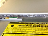
Remove the two Phillips screws from the optical drive (right) side of the computer:
-
Two 5.2 mm Phillips #00, with shank (2.3mm dia. x 3.25 mm len.) (Head: 3.2 mm. dia. x .5mm thick)
-
-
crwdns2935267:0crwdne2935267:0Plastic Cards$2.99
-
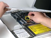
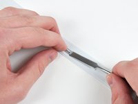
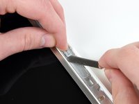
Use a plastic opening tool, an expired plastic credit, or a similarly-thick card to pry up on the upper case, starting in the upper-left corner and working around to the front of the computer.
-
-
-
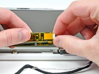
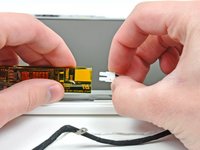
While holding up the upper case, pull up the black tab on the connector end of the silver ribbon cable away from the connector's socket on the logic board.
-
-
-
Grasp the white plastic tab attached to the hard drive and pull it to the left, removing the hard drive from the computer.
-
-
-
Remove the two Phillips screws from the side of the optical drive.
-
Two 3.25 mm Phillips #000 (head: 4 mm. dia. x .3 mm thick)
-
-
-
Disconnect the orange optical drive ribbon cable connector from the logic board by prying it straight up using either a finger or a spudger.
-
-
-
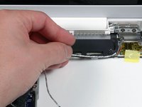
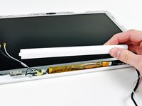
Disconnect the newly revealed display data cable's plug from the logic board by pulling it upward using its black pull-tab.
-
-
-
-
Disconnect the newly-revealed hard drive cable's plug from the logic board by pulling it upward using its black tab.
-
-
-
Peel up the foil tape between the fan and the optical drive. Lift the foil tape from the fan side, leaving it attached to the optical drive.
-
During reassembly, be sure to route the cables beneath the tape before reattaching it.
-
-
-
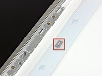
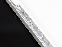
Pull up the display data cable from along the edge of the optical drive to reveal a silver Phillips screw.
-
-
-
Remove the 2 mm Phillips #00 screw securing the rear corner of the optical drive.
-
The silver-jacketed Bluetooth cable may be covering the screw. If so, carefully push it aside. You may need to remove the screw holding the ground shield lugs for the two nearby cables before you can move the Bluetooth cable aside sufficiently. This screw is 7mm in earlier models, and may be 4.2mm in Santa Rosa/Penryn and 2009 models.
-
-
-
Lift the Bluetooth antenna board from the front edge of the optical drive.
-
-
-
Deroute the hard drive cable from under the clips along the near side of the optical drive.
-
-
-
Lift the side of the optical drive closest to you, then slide the drive towards you, and up and out of the computer.
-
First, slide its side nearest to the rear of the Macbook under the edge of the rear frame to the left of the hinge, while also sliding the optical drive's mounting tab at its upper left corner under the cables at this location.
-
Lower the drive partially into the lower housing. Keep the hard drive cable away from the optical drive bay.
-
Before dropping the drive fully in place, use a spudger to push forward (towards the front of the drive) on the screw hole in the drive's mounting tab.
-
Push forward the slider, which runs along the far side of the drive, to insert the end of this slider into a small channel in the lower case's frame. This helps hold the drive in place.
-
-
-
For original Macbook Core Duo and Core 2 Duo models, remove these 3 screws:
-
Two 3 mm Phillips near the right speaker.
-
One 6 mm Phillips threaded through a hole in a plastic finger above the subwoofer.
-
For Santa Rosa/Penryn and 2009 models, which don't have a c-channel:
-
Remove only the single 3 mm Phillips screw from the right speaker, and skip step 26.
-
-
-
Lift the right speaker out of its housing and set it to the side.
-
-
-
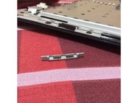
Using a spudger, gently pry up the white plastic slot and slide the metal c-channel to the right and away from the display.
-
-
-
Use a spudger to carefully disconnect the microphone cable from the logic board. You'll want to work from side to side, and slowly wiggle the plug back and out of its socket.
-
-
-
Lift up on the black right speaker cable with one hand, and deroute the microphone cable from the silver metal clip just above the right RAM slot.
-
-
-
If you didn't remove the ground lug retaining screw in step 20 above, remove it now. It's a 7mm (may be 4mm or 3mm in Santa Rosa/Penryn and 2009 models) Phillips screw securing the ground lugs on the right speaker cable and microphone cable to the metal frame.
-
-
-
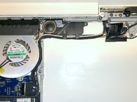
Deroute the microphone cable and the black display data cable from the tabs at the bottom of the subwoofer.
-
-
-
Remove the single 3 mm Phillips screw securing the ground lug in the display data cable located just above the Bluetooth board. This screw may also be securing a ground lug in the speaker cable.
-
-
-
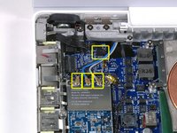
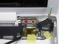
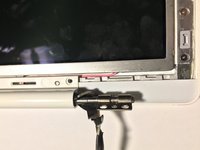
Disconnect the antenna cables from the Airport card:
-
If you have an original MacBook Core Duo or Core 2 Duo model, see the first picture, which shows that there are three antenna cables.
-
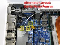
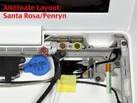
If you have a MacBook Core 2 Duo Santa Rosa/Penryn or 2009 model, there are only two antenna cables, and the plug/socket for the black inverter cable is in a different location. There may be a square foam piece over the plug/socket for the inverter board connector.
-
Disconnect the inverter cable from its socket by inserting a spudger between the right or left ends of the plug and the socket, and prying gently vertically. Do NOT pry up on the socket--you must pull up on the plug alone, vertically out of the socket. Do not pull in the direction of the cable wires or you will tear the socket off the logic board.
-
-
-
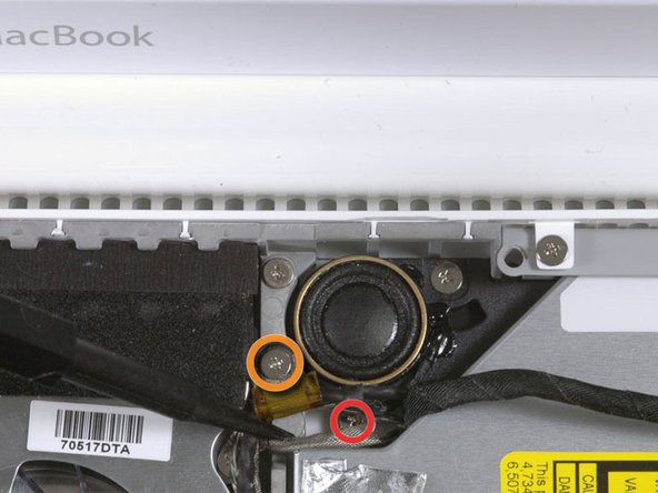
For original Macbook Core Duo and Core 2 Duo models, see first picture and remove the following 2 screws from the right hinge mount:
-
One 6 mm Phillips on the left side of the hinge mount.
-
One 10 mm Phillips on the right side of the hinge mount.
-
For Santa Rosa/Penryn and 2009 models, see second picture and remove the following 3 screws from the right hinge mount:
-
One 3 mm smalller diameter Phillips on the far left.
-
One 5.2 mm larger diameter, 4.2 mm head Phillips in the middle.
-
One 10 mm larger diameter, 4.2mm head Phillips from the far right.
-
Before removing the right hinge mount, take care to see how its pieces fit together, including the small white plastic piece. Knowing how the mount pieces fit together will help with reassembly. Lift the right hinge mount with the small white plastic piece out of the computer.
-
-
-
Hold the display with one hand while removing the following 3 screws from the left hinge mount:
-
One 7.2 mm smaller diameter Phillips from the right side.
-
One 5.2 mm larger diameter Phillips from the middle.
-
One larger diameter 10 mm Phillips from the left side.
-
Lift the left hinge mount with white plastic piece out of the computer.
-
Check that the cables coming out of the right end of the left hinge are not trapped under other cables.
-
-
-
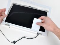
Grasp the display assembly on either side and lift it up and out of the computer, taking care that the cables attached to the display don't snag on parts in the lower case.
-
-
crwdns2935267:0crwdne2935267:0Plastic Cards$2.99
-
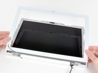
Use a thin plastic card to release the tabs and their clips holding the front display bezel to the display assembly. There are five tabs along the left side of the display bezel.
-
-
-
Continue to free the tabs along the the top edge of the display assembly.
-
-
-
Next, free the five tabs securing the display bezel on the right side.
-
-
-
Lift up the front display bezel from the top and use your plastic card to free the tabs along the bottom edge of the display bezel.
-
After freeing all holding tabs, lift the front display bezel away from the display assembly.
-
-
-
Use a metal spudger or another thin tool to carefully pry the gray plastic clips off the tabs molded into the front display bezel. A 0.8mm flat screwdriver may be useful for this step. You may find that it's easier to remove some of these clips by prying up on their long sides.
-
-
-
Insert one end of the retaining clip beneath the edge of its recess cut into the LCD bracket.
-
Use the edge of a spudger to push the short hook tab on the underside of the other end of the retaining clip into the recess cut into the LCD bracket.
-
-
-
Remove the three 4.2 mm Phillips screws securing the clutch cover.
-
-
-
While holding the display down with one hand, use your other hand to lift the left end of the clutch cover off the clutch hinge and guide the inverter cable and AirPort cables through the gap in the clutch cover. If the cables snag on the two hooked tabs on the inside end of the clutch cover, free them carefully.
-
-
-
Lift up the right end of the clutch cover while guiding the display data and iSight cables through the gap and the two hooked tabs at the right end of the clutch cover. If the cables snag on the two hooked tabs, free them carefully.
-
Lift the clutch cover off of the display assembly.
-
-
-
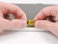
Slightly lift the newly-revealed inverter board out of its housing and disconnect the black inverter cable from the left end of the board.
-
-
-
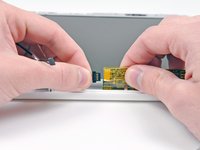
Disconnect the white inverter cable from the right end of the inverter board.
-
-
-
Remove the inverter board from the display.
-


To reassemble your device, follow these instructions in reverse order.
crwdns2935221:0crwdne2935221:0
crwdns2935229:0152crwdne2935229:0

crwdns2947412:08crwdne2947412:0
Awesome site and awesome guide. This exteneded the life of my MacBook. I can't thank you enough!!!!
stuartjwaldner - crwdns2934203:0crwdne2934203:0 crwdns2950251:0crwdne2950251:0
For about 3 years I had been dealing with my screen backlight shuting off. I would then dim the screen up and down until I could get it to stay. Sometimes it would work the first time other times I would be doing it for 10 minutes and other times I would give up for a few hours and come back and the screen would be on again. It would also do this sometimes when I opened the laptop at a certain angle or bumped the computer.
Well after these years very annoying behavior, my screen wont turn back on. I can see my desktop when I shine a light on the screen and hear the fan running so I know the computer works fine.
I've tried unpluging the inverter board to see if it was a loose connection, but that didn't work. I tried wiggling it around until the screen turned on and nothing.... Please help!
Is this a problem with my inverter or the inverter cable? Or the backlight cable?
What parts should I buy?
4321ora - crwdns2934203:0crwdne2934203:0 crwdns2950251:0crwdne2950251:0
Hi, I've had the same trouble. Today I solved with a spray electronic cleaner :)
19fra71 - crwdns2934203:0crwdne2934203:0 crwdns2950251:0crwdne2950251:0
Hi everybody! Last year bought a new inverter, new cable and other stuff and replaced. Problem not solved, screen still turning black. Thinking to get a new display, but today bought spray electronic cleaner, sprayed over the display data cable (https://d3nevzfk7ii3be.cloudfront.net/ig...). Problem &&^&^$^ solved! :) Time: 15 mins, money: 5$. Good tutorial tho! :P
19fra71 - crwdns2934203:0crwdne2934203:0 crwdns2950251:0crwdne2950251:0
These are a very comprehensive set of instructions and give a really good grand tour of the innards of a MacBook 8. They are also useful for replacing the hard drive or the optical drive.
Couple of hints:
1. Have on hand some canned compressed air - the inside of a laptop is generally quite full of dust and fluff.
2. Also have on hand some contact cleaner spray (do NOT use degreasers/lubricants/anti rust sprays such as RP 7 or WD 50). Contact cleaner sprays generally only contact isopropyl alchohol. It's good to give exposed contacts a bit of a clean - even grease from fingertips can affect conductivity and hence performance. (If possible, use powder free surgical gloves).
3. Make sure you have the right tools (don't skimp - buy the tools set from iFixit). Not using the right spudger on a plug could be the cause of irreparable damage to the circuit board.
(continued next posting)
brightvt - crwdns2934203:0crwdne2934203:0 crwdns2950251:0crwdne2950251:0