crwdns2915892:0crwdne2915892:0
How to remove the hard drive connector.
crwdns2942213:0crwdne2942213:0
-
-
Use a coin or spudger to rotate the battery-locking screw 90 degrees clockwise.
-
-
-
Lift the battery out of the computer.
-
-
-
Unscrew the three evenly-spaced Phillips screws from along the rear wall of the battery compartment.
-
-
-
Grasp the right end of the L-shaped memory cover, then pull it towards you so it clears the battery compartment opening.
-
Lift the memory cover up and out of the computer.
-
-
-
Remove the following 3 screws:
-
One 11 mm Phillips#00 in the middle of the lower case. (Head: 5mm dia. x .75mm thick)
-
Two 14.5 mm Phillips #00 (Head: 5mm dia. x .75mm thick)
-
-
-
Remove the following 3 screws from the rear wall of the battery compartment:
-
One 3 mm Phillips #0. (Head: 2.75 mm. dia.)
-
Two 4 mm Phillips #0 on the either side. (Head: 2.75mm dia.)
-
-
-
Remove the two Phillips screws from either side of the right wall of the battery compartment (not the ones closest to the battery connector).
-
Two 6.25 mm Phillips #000. (Head: 4 mm. dia. x .5mm thick)
-
-
-
-
Remove the four indicated Phillips screws from the front wall of the battery compartment. When working from the left, remove the 2nd, 4th, 7th and 9th screws.
-
Four 3.25 mm Phillips #000. (Head: 4 mm. dia. x 4mm thick)
-
-
-
Remove the following 4 screws from the back of the computer:
-
Two 11 mm Phillips #00, with Shank (2.2mm dia. x 2 mm len.) (Head: 3.2 mm. dia. x .5mm thick)
-
Two 7.25 mm Phillips #00, with Shank (2mm dia. x 3.75 mm len.) (Head: 3.2 mm. dia. x .5mm thick)
-
-
-
Remove the two Phillips screws from the optical drive (right) side of the computer:
-
Two 5.2 mm Phillips #00, with shank (2.3mm dia. x 3.25 mm len.) (Head: 3.2 mm. dia. x .5mm thick)
-
-
crwdns2935267:0crwdne2935267:0Plastic Cards$2.99
-
Use a plastic opening tool, an expired plastic credit, or a similarly-thick card to pry up on the upper case, starting in the upper-left corner and working around to the front of the computer.
-
-
-
While holding up the upper case, pull up the black tab on the connector end of the silver ribbon cable away from the connector's socket on the logic board.
-
-
-
Use the white plastic pull-tab to slide the hard drive to the left and out of the computer.
-
-
-
Disconnect the orange optical drive ribbon cable from the logic board.
-
-
-
Disconnect the newly-revealed display data cable. If there is no pull-tab on the top of the connector, it may be helpful to use a spudger to disconnect this connector.
-
-
-
Disconnect the (once again) newly-revealed hard drive cable.
-
-
-
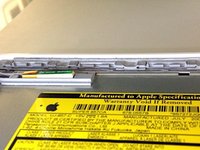
Deroute the hard drive connector cable from the four tabs along the edge of the optical drive.
-
-
-
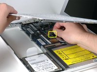
Remove the two Phillips screws securing the hard drive connector to the lower case.
-
-
-
Carefully lift the hard drive connector out of the case slightly, and turn it over to reveal the IR sensor connector beneath. Use a spudger to flip up the tiny bar holding the cable in place.
-
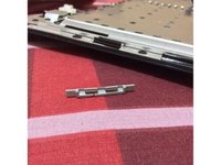
Slide the orange IR sensor cable out of its connector, and lift the hard drive connector out of the computer.
-


To reassemble your device, follow these instructions in reverse order.
To reassemble your device, follow these instructions in reverse order.
crwdns2935221:0crwdne2935221:0
crwdns2935229:039crwdne2935229:0

crwdns2947410:01crwdne2947410:0
Thanks for this very details explanation…very useful to me ;)