crwdns2915892:0crwdne2915892:0
Charges battery and connects battery to logic board.
crwdns2942213:0crwdne2942213:0
-
-
Use a coin or spudger to rotate the battery-locking screw 90 degrees clockwise.
 crwdns2952109:0crwdne2952109:0
-
-
-
Lift the battery out of the computer.
-
-
-
Unscrew the three evenly-spaced Phillips 000 screws from along the rear wall of the battery compartment.
-
-
-
Grasp the right end of the L-shaped memory cover, then pull it towards you so it clears the battery compartment opening.
-
Lift the memory cover up and out of the computer.
-
-
-
Remove the following 3 screws:
-
One 11 mm Phillips#00 in the middle of the lower case. (Head: 5mm dia. x .75mm thick)
-
Two 14.5 mm Phillips #00 (Head: 5mm dia. x .75mm thick)
-
-
-
Remove the following 3 screws from the rear wall of the battery compartment:
-
One 3 mm Phillips #0. (Head: 2.75 mm. dia.)
-
Two 4 mm Phillips #0 on the either side. (Head: 2.75mm dia.)
-
-
-
-
Remove the two Phillips screws from either side of the right wall of the battery compartment (not the ones closest to the battery connector).
-
Two 6.25 mm Phillips #000. (Head: 4 mm. dia. x .5mm thick)
-
-
-
Remove the four indicated Phillips screws from the front wall of the battery compartment. When working from the left, remove the 2nd, 4th, 7th and 9th screws.
-
Four 3.25 mm Phillips #000. (Head: 4 mm. dia. x 4mm thick)
-
-
-
Remove the following 4 screws from the back of the computer:
-
Two 11 mm Phillips #00, with Shank (2.2mm dia. x 2 mm len.) (Head: 3.2 mm. dia. x .5mm thick)
-
Two 7.25 mm Phillips #00, with Shank (2mm dia. x 3.75 mm len.) (Head: 3.2 mm. dia. x .5mm thick)
-
-
-
Remove the two Phillips screws from the optical drive (right) side of the computer:
-
Two 5.2 mm Phillips #00, with shank (2.3mm dia. x 3.25 mm len.) (Head: 3.2 mm. dia. x .5mm thick)
-
-
crwdns2935267:0crwdne2935267:0Plastic Cards$2.99
-
Use a plastic opening tool, an expired plastic credit, or a similarly-thick card to pry up on the upper case, starting in the upper-left corner and working around to the front of the computer.
-
-
-
While holding up the upper case, pull up the black tab on the connector end of the silver ribbon cable away from the connector's socket on the logic board.
-
-
-
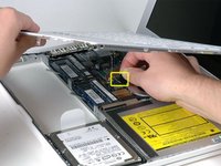
Remove the single Phillips screw near the battery connector.
-
-
-
Remove the small black plastic spacer from the computer.
-
-
-
Remove the two Phillips screws attaching the battery connector to the lower case.
-
-
-
Use a spudger to carefully pry the battery connector up and disconnect it from the logic board.
-
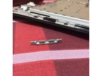
Look at the pinout on the bottom of the battery connector circuit board. If there's no gap in the two rows of pins (if both rows contain ten pins), it's the Non-Energy Star version. If there is a gap (two rows of six pins each, separated from two rows of three pins each), then it's the Energy Star version. These two versions aren't interchangeable.
-


To reassemble your device, follow these instructions in reverse order.
crwdns2935221:0crwdne2935221:0
crwdns2935229:052crwdne2935229:0

crwdns2947412:04crwdne2947412:0
plz add screw size
Arash Masoum - crwdns2934203:0crwdne2934203:0 crwdns2950251:0crwdne2950251:0
Im sad i did this one + Replacing MacBook Core 2 Duo Magsafe Board, try another charger and still the same symptoms :( wont charge and green light stay on. waste of time and money for my Macbook 2.4Ghz intel core 2 DUO White.
cosmosquad - crwdns2934203:0crwdne2934203:0 crwdns2950251:0crwdne2950251:0
Did you ever resolve the issue? If so, what was the problem? Thank you.
Sherita Sims - crwdns2934203:0crwdne2934203:0 crwdns2950251:0crwdne2950251:0
My battery connector looks like the energy star (6+12 pins) but on the motherboard says “apple inc 820-2279-A “ and no ‘energy star’ is written. I assume I should get the energy star model because is identical to mine. However, iFixit points to follow what is written on the board. So, something wrong here…
daniel - crwdns2934203:0crwdne2934203:0 crwdns2950251:0crwdne2950251:0