crwdns2915892:0crwdne2915892:0
Use this guide to replace your MacBook Air's display assembly.
crwdns2942213:0crwdne2942213:0
-
crwdns2935267:0crwdne2935267:0P5 Pentalobe Screwdriver Retina MacBook Pro and Air$5.99
-
Remove the following ten screws:
-
Two 9 mm 5-point Pentalobe screws
-
Eight 2.6 mm 5-point Pentalobe screws
-
-
-
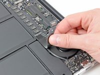
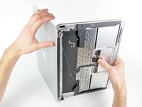
Wedge your fingers between the display and the lower case and pull upward to pop the lower case off the Air.
-
Remove the lower case and set it aside.
-
-
-
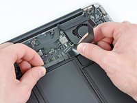
Grab the clear plastic pull tab attached to the battery connector and pull it toward the front edge of the Air to disconnect the battery from the logic board.
-
-
-
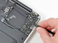
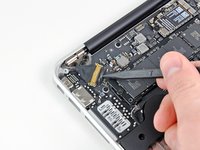
Use the flat end of a spudger to pry the I/O board cable connector upward out of its socket on the I/O board.
Die nachfolgenden Schritte sind nicht erforderlich. Bitte bei Schritt 11 weitermachen.
Es ist nicht erforderlich, IO-Board, Akku und Logic-Board auszubauen. Es genügt, die Antennen- das Kamera- und das Displaykabel zu entfernen und die Scharniere abzumontieren. Die Kabel können leicht an den vorhandenen Komponenten vorbeigezogen werden.
-
-
-
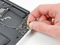
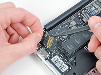
Carefully peel the I/O board cable from the top of the fan.
-
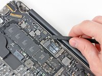
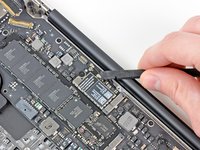
While gently pulling the I/O board cable upward near its connection to the logic board, use the tip of a spudger to pry upward on alternating sides of the connector to help "walk" it out of its socket.
-
Remove the I/O board cable.
-
-
-
Use the tip of a spudger to carefully flip up the retaining flap on the fan cable ZIF socket.
-
-
-
Peel the rubber gasket off the adhesive on the top of the fan.
-
-
-
Remove the following three screws securing the fan to the upper case:
-
One 3.6 mm T5 Torx screw
-
One 2.7 mm T5 Torx screw
-
One 3.6 mm T5 Torx screw with a short head
-
-
-
Lift the fan out of the upper case and carefully pull the fan ribbon cable out of its socket as you remove it from the Air.
-
-
-
Disconnect the I/O board by pulling the power cable away from its socket on the logic board.
-
-
-
Pull the camera cable parallel to the face of the I/O board toward the corner of the Air to disconnect it from its socket, using the tip of a spudger to help push the connector out of its socket.
Die nachfolgenden Schritte sind nicht erforderlich. Einfach bei Schritt 20 weitermachen.
-
-
-
Use the flat end of a spudger to pry the left speaker cable connector up and out of its socket on the I/O board.
-
De-route the left speaker cable from its retainer on the I/O board.
-
-
-
-
Use the flat end of a spudger to pry the microphone cable connector up and out of its socket on the I/O board.
-
-
-
Remove the single 3.6 mm T5 Torx screw securing the I/O board to the upper case.
When inserting new board, make sure the headphones jack socket rim is registered properly with the case hole before tightening T5 screw.
-
-
-
Carefully lift the I/O board from its edge nearest the logic board and remove it from the upper case.
-
-
-
Remove the following five screws securing the battery to the upper case:
-
Three 6.3 mm T5 Torx screws
-
Two 2.4 mm T5 Torx screws
-
-
-
Lift the battery from its edge nearest the logic board and remove it from the upper case.
-
-
-
Use the tip of a spudger or your fingernail to flip up the retaining flap on the trackpad ribbon cable ZIF socket.
-
Pull the trackpad ribbon cable straight out of its socket toward the front edge of the Air.
-
-
-
Use the flat end of a spudger to pry the right speaker cable connector up and out of its socket on the logic board.
-
-
-
Gently push the tip of a spudger under the black plastic flap stuck to the display data cable lock to make the lock pop upward and away from the socket.
-
While holding the lock away from the socket, use the tip of a spudger and your fingers to gently remove the display data cable from its socket by sliding it toward the corner of the Air.
-
-
-
Use the flat end of a spudger to pry both antenna cable connectors up and off their sockets on the AirPort/Bluetooth card.
When you are assembleIng , you shoud this phase at settin mother board
-
-
-
Gently de-route the antenna cables from the slot cut into the logic board.
-
-
-
Remove the single 2.85 mm T5 Torx screw securing the SSD to the logic board.
-
-
-
Pull the drive straight out of its socket and remove it from the logic board.
-
-
-
Remove the six 6.3 mm T5 Torx screws securing the logic board to the upper case.
-
-
-
Remove the inner two 4.9 mm T8 Torx screws securing the antenna cable retainer and left clutch hinge to the upper case.
-
-
-
Push the antenna cable retainer away slightly and remove the 3 mm T5 Torx screw securing the end of the heat sink to the upper case.
-
-
-
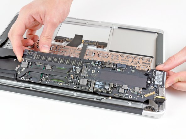
Carefully remove the logic board assembly from the upper case, minding any cables that may get caught.
Really great guide!!!
My only issue was the removal of the logic board was a bit nerve wracking.
The speaker wire was stressed heavily as the board tilted up. Removing the speakers before the board would solve this.
I did it in that order during reassembly, and it worked great.
I also had an issue with the logic board installation as the above comment mentioned. I found easiest way is to just remove the speaker that you just re-installed. It's 1 screw - take that speaker out and now that wire that was bumping logic board is out of the way, and just then re-install the speaker.
When replacing the logic board, make sure the two rf connectors are out of the way before you put the screws back.
-
-
-
Gently de-route the antenna cables out of the channel cut into the upper case.
-
-
-
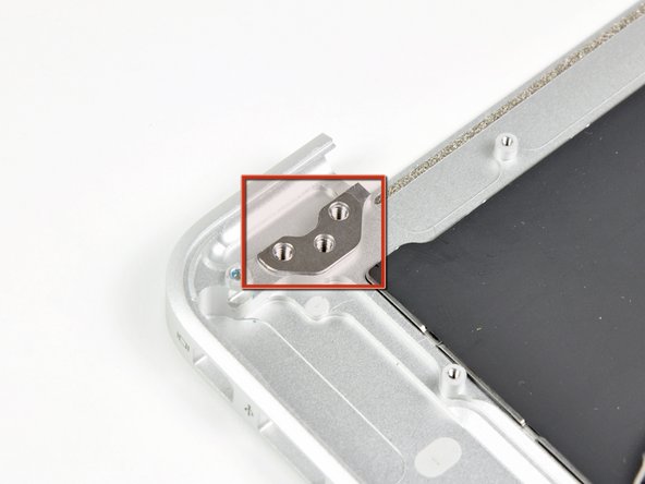
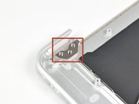
Remove the inner two 4.9 mm T8 Torx screws securing the right display hinge to the upper case.
-
-
-
Open the display until it is perpendicular to the upper case and place it on a table as shown.
-
While holding the Air steady, remove the remaining 4.9 mm T8 Torx screw from the lower display bracket.
-
-
-
Remove the last 4.9 mm T8 Torx screw securing the display to the upper case.
-
-
-
Push the upper case slightly toward the display assembly, then rotate it away from the front of the display assembly.
-
Once the two display hinges have cleared the upper case, remove the display and set it aside.
-


To reassemble your device, follow these instructions in reverse order.
To reassemble your device, follow these instructions in reverse order.
crwdns2935221:0crwdne2935221:0
crwdns2935229:073crwdne2935229:0

crwdns2947412:012crwdne2947412:0
Perfect! Thank You!
Removing the logic board is completely unnecessary and you risk damaging more components. Follow steps 1-3, 11, 20-22, 26, 30-34. Obviously be careful not to damage the board when you are actually taking the display off.
Beau is correct . It isn't necessary at all to remove the logic board. Steps 1-3, 11, 20-22, 26, 30-34 are all that needs to be done.
For screen replacement only i did not have to remove board. So steps 16-19, 23-25, 29 are not needed.
Be careful on the step 12, my speaker connector fell off, I had to do some soldering to fix that. It is very gentle.
Excellent guide, however, I would like to note that removing the logic board is completely unnecessary. In the process of doing so, I ended up breaking my right speaker socket from the logic board. The simpler method is to just unscrew the display hinge, antenna, and isight cable, then remove and replace display.
Beau and Radiant Tech, should these steps also be skipped for the 11 inch Air display replacement? Avoiding removal of the logic board would be a bonus.
Just did it following the shortened instructions…. doable, but not for the faint of heart. Thank you iFixIt. Repair is noble and a MacBook Air 13 inch late 2010 is back on duty. My daughter is over the moon.
IS the keyboard user replaceable?
Used this guide to switch the displays of two identical Macbooks, very in depth, very useful knowledge on the late 2010 MBA.
Hat hervorragend geklappt. Vielen Dank.
I did it with the shortened steps. For reassembly I positioned the bottom case with logic board on a large enough cardboard box so that the screen assembly could hang at 90 degrees. This allowed me to insert the shims properly.
Agree with the previous comment. This task requires only the antennae, camera, and video to be disconnected. The only fiddly bit is disengaging and then reconnecting the hinges...with the shims. Having the case horizontal and supporting the screen makes it much easier, unless you were born with 4 arms.