crwdns2915892:0crwdne2915892:0
Use this guide to replace the heat sink, or remove it for reapplication of thermal paste.
Be sure to apply a new layer of thermal paste before reinstalling your heat sink.
crwdns2942213:0crwdne2942213:0
-
crwdns2935267:0crwdne2935267:0P5 Pentalobe Screwdriver Retina MacBook Pro and Air$5.99
-
Use a P5 Pentalobe driver to remove ten screws securing the lower case, of the following lengths:
-
Two 9 mm screws
-
Eight 2.6 mm screws
-
-
-
Wedge your fingers between the display and the lower case and pull upward to pop the lower case off the Air.
-
Remove the lower case and set it aside.
-
-
-
Grab the clear plastic pull tab attached to the battery connector and pull it parallel to the board toward the front edge of the Air.
-
-
-
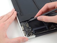
Use the flat end of a spudger to pry the I/O board cable connector up out of its socket on the I/O board.
-
-
-
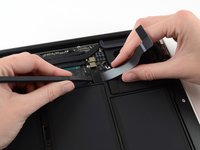
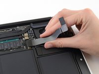
Carefully peel the I/O board cable from the adhesive securing it to the top of the fan.
-
-
-
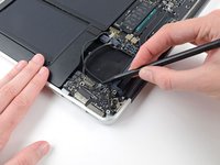
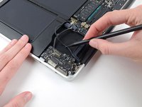
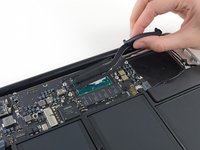
While gently pulling the I/O board cable upward near its connection to the logic board, use the flat end of a spudger to pry up on alternating sides of the connector to help "walk" it out of its socket.
-
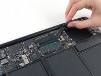
Remove the I/O board cable.
-
-
-
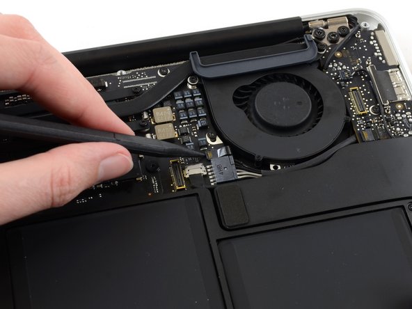
Use the tip of a spudger to carefully flip up the retaining flap on the fan cable ZIF socket.
-
-
-
-
Peel the rubber gasket off the adhesive on the top of the fan.
-
-
-
Remove the following three screws securing the fan to the upper case:
-
One 5.2 mm T5 Torx screw
-
One 3.3 mm T5 Torx screw
-
One 4.4 mm T5 Torx screw with a short head
-
-
-
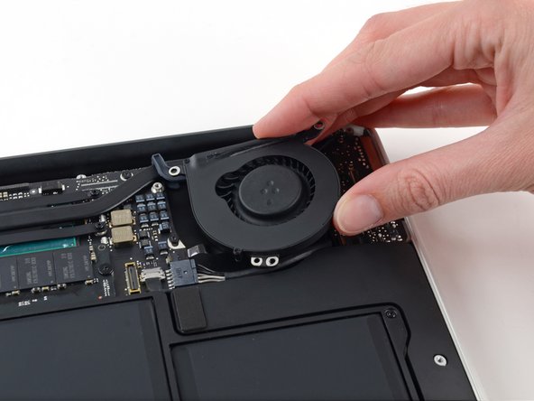
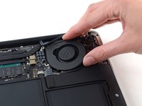
Lift the fan from the I/O board side and pull it free from the upper case.
-
Removing the fan will also disconnect the fan ribbon cable. Be careful not to snag it.
-
-
-
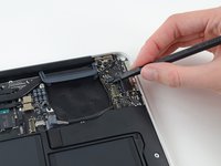
Disconnect the I/O board by pulling its power cable away from its socket on the logic board.
-
-
-
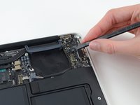
Use the flat end of a spudger to pry the left speaker cable connector up and out of its socket on the I/O board.
-
-
-
Use the tip of a spudger to carefully flip up the retaining flap on the microphone ribbon cable ZIF socket.
-
-
-
Remove the single 4.1 mm T5 Torx screw securing the I/O board to the upper case.
-
-
-
Gently de-route the camera cable from its notch on the I/O board and push it out of the way with the tip of a spudger.
-
-
-
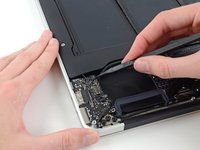
Lift the I/O board from the logic board side and pull it free from the upper case.
-
Removing the I/O board will also disconnect the microphone ribbon cable. Be careful not to snag it.
-
-
-
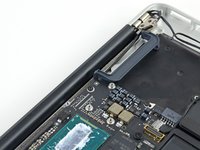
Remove the two 4.9 mm T8 Torx screws securing the antenna cable retainer on the left display hinge to the upper case.
-
-
-
Push the antenna cable retainer out of the way and remove the single 3 mm T5 Torx screw securing the end of the heat sink to the upper case.
-
-
-
Remove the four 2.5 mm T5 Torx screws securing the heat sink to the logic board.
-
-
-
Remove the heat sink from the logic board.
-


To reassemble your device, follow these instructions in reverse order.
Take your e-waste to an R2 or e-Stewards certified recycler.
Repair didn’t go as planned? Try some basic troubleshooting, or ask our Answers community for help.
To reassemble your device, follow these instructions in reverse order.
Take your e-waste to an R2 or e-Stewards certified recycler.
Repair didn’t go as planned? Try some basic troubleshooting, or ask our Answers community for help.
crwdns2935221:0crwdne2935221:0
crwdns2935229:011crwdne2935229:0

crwdns2947412:03crwdne2947412:0
Well imho a lil bit overkill from step 11 - you can easily unscrew with thin screwdriver the lonely heatsink screw near the rubber component
is the tr8 torx screw a neccessity and if so what step
is a tr8 torx security screwdriver a necessity? if so what step?