crwdns2915892:0crwdne2915892:0
Use this guide to replace the logic board in a 2018 MacBook Air.
Note that Touch ID will not function after replacing the logic board. The MacBook’s original Touch ID sensor is uniquely paired to the T2 chip on the logic board at the factory—and without Apple’s proprietary calibration process, even a genuine replacement logic board from another MacBook Air won’t work.
If you replace the logic board, you must install a paired Touch ID sensor to retain Touch ID functionality.
crwdns2942213:0crwdne2942213:0
-
-
If your MacBook is running Big Sur v11.1 or later, disabling Auto Boot may not work. You can proceed normally, but make sure to disconnect the battery as soon as you're inside.
-
Use a P5 driver to remove the following screws:
-
Two 7.9 mm screws
-
Two 7.1 mm screws
-
Six 2.6 mm screws
-
-
-
Wedge your fingers between the display and the lower case and pull upward to pop the lower case off the Air.
-
Remove the lower case.
-
-
-
Peel back the tape covering the battery connector enough to reveal the connector underneath.
-
-
-
Use a spudger to slide the battery connector parallel to the logic board and out of its socket on the logic board.
-
-
-
Use a T3 Torx driver to remove the two 1.4 mm screws securing the trackpad connector bracket.
-
Remove the trackpad connector bracket.
-
-
-
Use the flat end of a spudger to pry the trackpad cable connector up and out of its socket.
-
-
-
-
Slide the tip of a spudger underneath the left speaker cable and pry straight up to disconnect the speaker.
-
With the connector disconnected, slide the flat end of a spudger under the cable to separate the adhesive securing the cable to the logic board.
-
-
-
Use a T3 Torx driver to remove the two 1.3 mm screws securing the USB-C port connector bracket.
-
Remove the USB-C connector bracket.
-
-
-
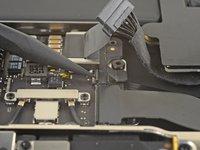
Use the flat end of a spudger to pry the USB-C cable connector up and out of its socket on the logic board.
-
-
-
Use a spudger to lift up the small locking flap on the sound board cable's ZIF connector.
-
Slide the sound board cable out of the ZIF connector.
-
-
-
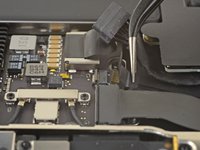
Peel back the black tape covering the fan cable connector.
-
-
-
Use the tip of a spudger to lift up the locking flap on the fan cable's ZIF connector.
-
Slide the fan cable out of the ZIF connector.
-
-
-
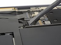
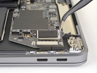
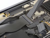
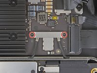
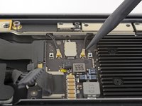
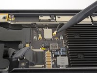
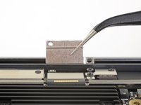
Use a T3 Torx driver to remove the two 1.4 mm screws securing the antenna cable bracket.
-
Remove the antenna cable bracket.
-
-
-
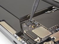
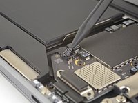
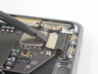
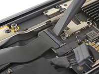
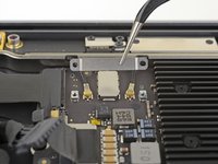
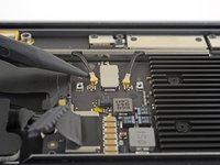
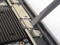
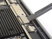
Insert the point of a spudger under one of the antenna cables close to the connector. Pry straight up to disconnect the cable.
-
Repeat for the other antenna cable.
-
-
-
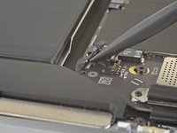
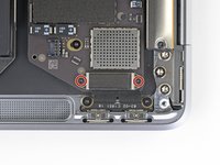
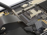
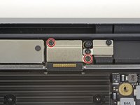
Use a T3 Torx driver to remove the two 1.5 mm screws securing the display cable connector bracket.
-
Remove the display cable connector bracket.
-
-
-
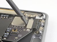
Use the flat end of a spudger to pry up the display cable connector.
-
-
-
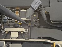
Use a T5 Torx driver to remove the following screws:
-
One 5.5 mm screw
-
Three 2.6 mm screws
-
Two 1.9 mm screws
-
-
-
Remove the logic board.
-


Compare your new replacement part to the original part—you may need to transfer remaining components or remove adhesive backings from the new part before installing.
To reassemble your device, follow the above steps in reverse order.
Take your e-waste to an R2 or e-Stewards certified recycler.
Repair didn’t go as planned? Check out our Answers community for troubleshooting help.
crwdns2935221:0crwdne2935221:0
crwdns2935229:013crwdne2935229:0

crwdns2947410:01crwdne2947410:0
Some very useful Comments from other users ... thanks to all of you for taking the time to write!