crwdns2915892:0crwdne2915892:0
Use this guide to replace the logic board.
Removing the logic board means you'll need to reapply a layer of thermal compound.
Before beginning any work on your Mac Pro: Unplug the computer and press and hold the power button for ten seconds to discharge the power supply's capacitors.
Be very careful not to touch the capacitor leads or any exposed solder joints on the back of the power supply. Only handle the board by the edges.
crwdns2942213:0crwdne2942213:0
-
-
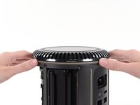
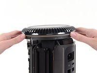
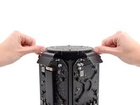
Slide the lock switch to the right, to the unlocked position.
-
-
-
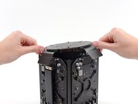
Lift the outer case straight up off the Mac Pro.
-
-
-
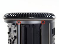
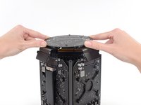
Remove five 5.1 mm T10 Torx screws from around the outer perimeter of the fan assembly.
You don't have to remove the fan assy to get to the wifi board & card. It can be done with the fan assy still attached.
Fat Mango is correct. That said. If you do pull the fan assembly note that the screws are all held in with blue Permatex and breaking them free takes a fair amount of effort. Getting a good set of Torx screwdrivers is a must.
Hey guys, what would happen if you only replace one card.. I have a D300 but the plan is to upgrade to D500 or D600. So If I can afford and install one instead of the pair would it increase something? or will it cause any conflict? I guess I don’t understand if I the Mac Pro has 2 D300 graphic cards that means each has 1GB? Same as If I would Install 1 D600 that would increase 3GB only? Thanks.
D300 = 2GB each card. Very few apps uses two cards at the same time.
Gio Cas -
The (5) Screws are Apple part number 923-0713
-
-
-
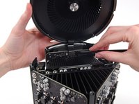
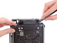
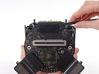
Tilt the assembly up away from the IO board.
-
-
-
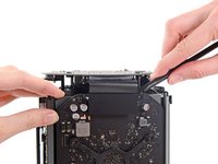
While supporting the fan assembly with one hand, loosen the two T8 captive screws in the fan cable bracket.
On my Mac Pro (assembled mid-2017) these are T8 screws. In fact, there were no T7 screws anywhere in my machine.
There was no bracket on top of the cable at all, so I got a bit confused, so I had to skip step 5 and 6.
On my machine, a TR7 worked to remove them due to the weird angle.
-
-
crwdns2935267:0crwdne2935267:0Tweezers$4.99
-
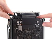
Use a pair of tweezers to pull the fan cable bracket away from the fan assembly.
-
-
-
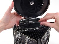
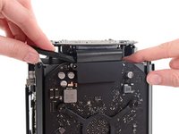
Use the flat end of a spudger to disconnect the fan assembly ribbon cable from the IO board.
-
-
-
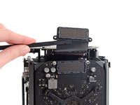
Disconnect the fan assembly antenna cable from the IO board.
-
Remove the fan assembly from the Mac Pro.
You don't have to remove the fan assy to do the steps below. They can be done with the fan assy still attached.
-
-
-
Remove five 5.1 mm T10 Torx screws from the outer perimeter of the lower case.
-
-
-
-
Carefully lift the lower case up and remove it from the Mac Pro.
-
-
-
Use the flat end of a spudger and a twisting motion to gently separate one side of the graphics card data connection.
-
-
-
Gently separate the other side as well.
-
Flip the connector up and out of the way of the graphics card.
-
-
-
Remove the two 6.0 mm T8 Torx screws securing the interconnect board to the heat sink.
These are actually 6.0mm T8 Torx Screws. 12/07/2016.
Ended up being T9 screws for me.
On my Mac Pro (assembled mid-2017) these are T8 screws. In fact, there were no T7 screws anywhere in my machine.
These are T8 screws in my 2013 Mac Pro.
T8 screws for me, i did and edit to this step
Ended up being T15 screws on my machine
-
-
-
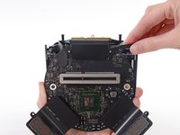
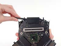
Gently walk the interconnect board straight up off the logic board's slot connection.
-
-
-
Flip the interconnect board up and over, exposing the IO board data cable.
-
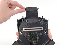
Use the same sort of twisting and spreading motion with the flat end of a spudger to separate one side of the IO board data cable.
-
-
-
Use the flat end of a spudger to separate the other side of the IO board data cable.
-
Bend the cable out of the way and remove the interconnect board from the Mac Pro.
-
-
-
Flip the Mac Pro back over and set it gently on a flat surface.
-
-
-
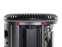
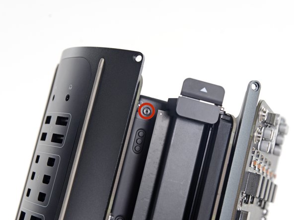
Remove the two 3.6 mm T5 Torx screws from the sides of the power supply cage (one on each side).
those are t4 screws in my mac
T4s on mine, as well
-
-
-
Remove the power supply cage from the top of the power supply.
-
-
-
Remove the four 5.5 mm T8 Torx screws securing the power supply assembly to the Mac Pro.
-
-
-
Remove the power supply assembly from the Mac Pro.
-
-
-
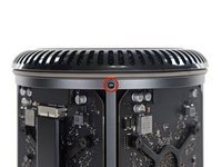
Remove two 5.5 mm T8 Torx screws.
Il est possible de les retirer aussi des le début une fois le “fond” rond du Mac pro retiré
Step 22 when reassembling, it helps not to fully tighten until you put the screws in from step 20.
-
-
-
Remove four 12.8 mm T10 Torx screws from the CPU heat sink bracket.
I cannot unscrew one of those because I appears that one of the elements in wich it is screwd underneath is loose and moving along with the screw, making this operation impossible. Anyone had this issue ?? Any solution ??
I had the same problem. These screws go into threaded inserts, which in turn are screwed into the heatsink. Both have threadlocker compound applied. So the threaded insert’s threadlocker gives up first, and the threaded insert unscrews from the heatsink. Remove all 4 screws, then with a pair of needle nose pliers, hemostat, or thin 7mm wrench, hold the insert steady and unscrew the screw from it.
Could I remove these screws and re-screw? I worry that remove them but I can’t re-use them?
timmy123 -
I had that problem, too, and I did it like Chuck Fry, with a thin wrench. Unfortunately one threaded insert was so tight that I slipped and a capacitor broke off. Can someone tell me what kind of capacitor I need? I can't find anything under the name listed above the capacitor. Thank you.
A way to avoid this situation is to ease the tension on the spring slowly and rotate the loosening of four screws a few turns at a time – when the tension is released equally the threaded inserts are more likely to stay in place.
I had 2 of those double sided screws stuck like that. I carefully removed them from the motherboard using a small vice grip to hold one side, and a torx on the other. Then reinstalled them using locktite compound. Make sure the heat sink is flush to the motherboard in the same way that you found it, or the assembly will not fit back in the case correctly, indicating the CPU may not be securely attached. The result may be that you think you killed your mac when you turn in on again and just hear the fan spinning like crazy but no chime or boot sequence. If that happens, go back in, reset the double sided screws, and make sure the heatsink is flush. Worked for me.
-
-
-
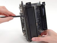
Remove the logic board from the heat sink.
-
-
-
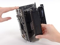
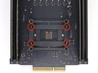
Remove the inner four 12.8 mm T10 Torx screws from the CPU heat sink bracket.
-
Remove the CPU heat sink bracket.
On my Mac Pro (assembled mid-2017) these screws are covered with a black sticker presumably to indicate tampering. If you did not know they were screws it would not be obvious. You have to just put the T10 driver right in the center and start turning; it quickly breaks through the sticker.
Oh man. Thanks so much for that comment! I would have tried to use pliers!
Also remember to support the CPU (On the other side) while removing these screws. Mine CPU fell out from the other side while loosening.
On my MacPro there are no screws here. On the backside the place where the back of the screws should be are covered with stickers, but removing the stickers simply reveals a rivet. There’s no screw and seemingly no way to remove the CPU.
Je confirme, un sceau plastique noir protège les 4 vis. Il faut percer et dévisser au centre avec t9 pour moi
Wow, glad I clicked comments. I had no clue about the sticker. I was about to use some kind of something to get them out 😂
-
-
-
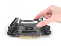
Remove the second heat sink bracket.
-
-
-
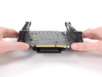
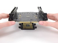
Lift and remove the logic board from the CPU and bracket.
-
During reassembly, be sure to clean off and replace the thermal compound on the CPU.
-
We have a thermal paste guide that makes replacing the thermal compound easy.
There is one import piece of information when replacing or upgrading these processors. There are two possible orientations and only one is correct (correct me if I’m wrong!). There’s a small arrow on one corner of the processor that needs to be aligned to the correct side. Just match the orientation of the original processor - this can be difficult or easy to overlook since the tiny alignment arrow is usually covered with thermal paste. Clean the Thermal paste off the old processor before you remove it to see the correct alignment.
-


To reassemble your device, follow these instructions in reverse order.
To reassemble your device, follow these instructions in reverse order.
crwdns2935221:0crwdne2935221:0
crwdns2935229:014crwdne2935229:0

crwdns2947410:01crwdne2947410:0
The RAM/CPU board is only attached to the thermal core around the processor area. This means seating RAM modules can flex the board (which has no support under the RAM sockets) so take extra care seating RAM modules.