crwdns2915892:0crwdne2915892:0
Over time, the USB cable on your Logitech F310 Gamepad controller may become damaged, leading to connection issues. This guide will walk you through replacing the USB cable in a Logitech Gamepad F310 (Model G-U0001), including desoldering the old cable and soldering a new one.
This repair requires the careful handling of electronic components and using a soldering iron. The soldering iron can get very hot and will burn so be careful when operating it.
Before you begin this repair, make sure that your controller is turned off and unplugged from the console. It's also important to unplug or remove the battery.
crwdns2942213:0crwdne2942213:0
-
-
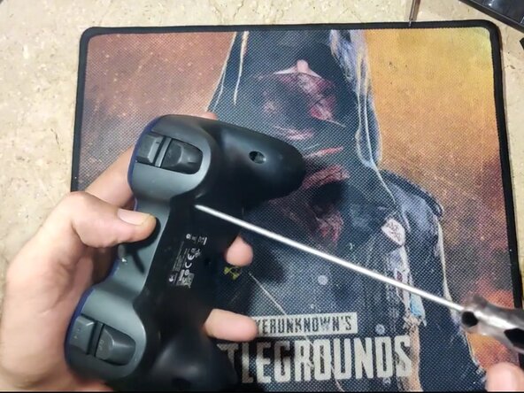
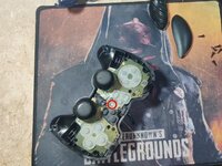
Turn the controller face-down on a soft surface.
-
Use a Phillips #1 screwdriver to remove the seven, 10 mm screws from the back shell.
-
-
-
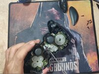
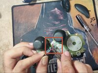
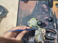
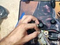
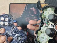
Use a plastic opening tool or spudger to release the clips holding the top and bottom of the controller together and separate the housing.
-
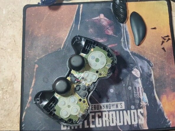
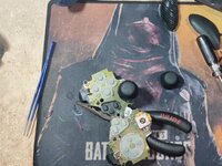
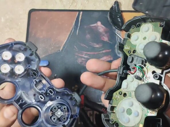
Lift the back shell to expose the circuit board and cable.
-
-
-
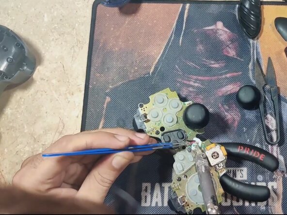
Use a Phillips #1 screwdriver to remove the single 6 mm screw securing the circuit board to the bottom shell.
-
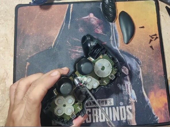
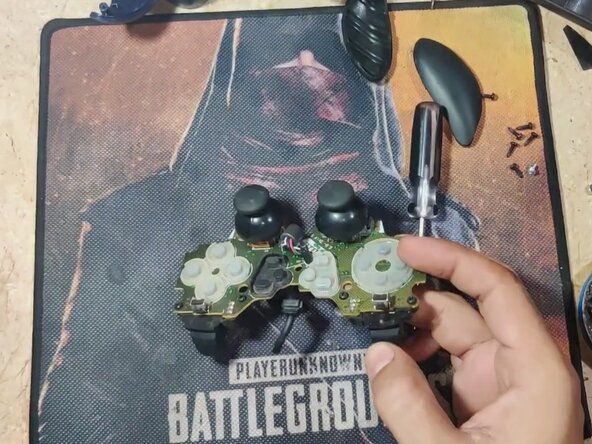
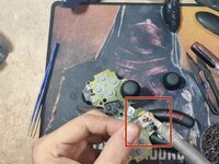
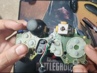
Gently lift the circuit board from the rear shell to access the solder points for the USB cable.
-
-
-
-
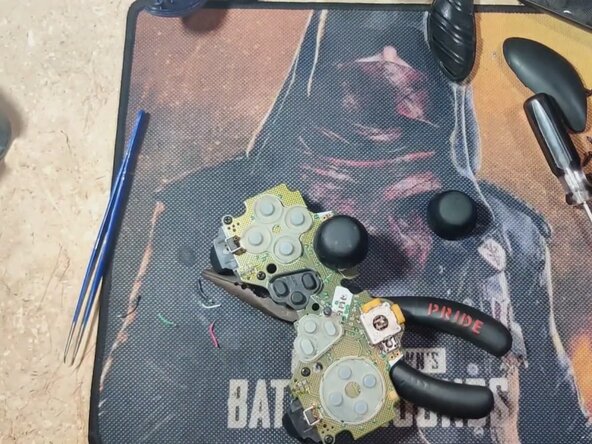
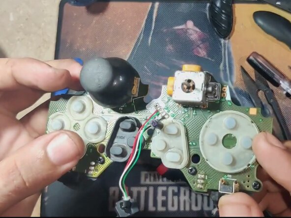
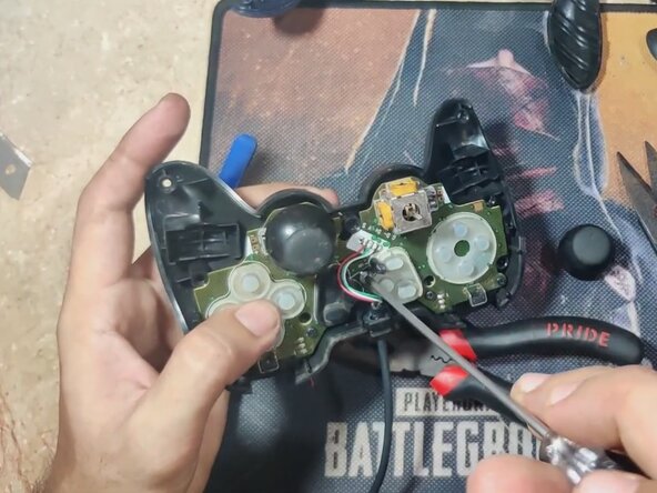
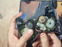
Cut the five wires to the damaged cable with a wire cutter first to make handling easier.
-
Use a soldering iron and wick or desoldering pumpto remove solder from each of the five pins.
-
Carefully remove each wire with tweezers once desoldered.
-
-
-
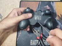
Use a wire stripper to strip the ends of the five wires on your replacement cable if it's not already done.
-
Tin the ends of each wire.
-
Match the wire colors to the board’s labeled pads (usually: VCC, D-, D+, GND, Shield).
-
Solder each wire carefully to its correct pad.
-
-
-
Route the new cable along the original path and ensure it sits flat in the groove.
-
Place the circuit board back into the back shell.
-
Use a Phillips #1 to replace the 6 mm screw.
-
Realign the buttons and membranes in the front shell if any were dislodged.
-
Snap the front and back halves together, ensuring nothing is pinched or out of place.
-
-
-
Replace the seven 10 mm-long PH1 screws.
-


To reassemble your device, follow these instructions in reverse order.
To reassemble your device, follow these instructions in reverse order.

crwdns2915084:0crwdne2915084:0

CSU Los Angeles, Team 3-13, Grodsky Spring 2025 crwdns2935289:0CSU Los Angeles, Team 3-13, Grodsky Spring 2025crwdne2935289:0
CSULA-GRODSKY-S25S3G13
crwdns2934841:01crwdne2934841:0
crwdns2935303:01crwdne2935303:0