crwdns2942213:0crwdne2942213:0
-
-
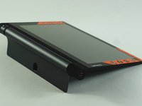
Open the built-in kickstand.
-
-
-
Remove the sticker located directly under the the built-in kickstand to reveal two 0.75 mm screws.
-
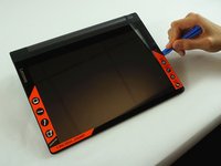
Remove the microSD card slot cover. Remove any microSD card (if inserted).
-
Using a Phillips head screwdriver, remove the three 0.75 mm screws.
On 3 plus model the third screw is not under microSD card but rather under a small sticker on the right side. Plus has longer battery.
on the Tab 3 plus , the third screw is not under the sd card but a little further over under another sticker and is painted white
-
-
-
-
Orient the device so the screen is facing you.
-
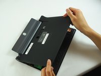
Carefully insert the spudger along the seam between the screen and back cover and gently separate the back cover from the device frame.
-
Continue to detach the backplate from the frame by moving the spudger around the perimeter.
On some models there is glue pad under the sim/sdcard tray.
Ein Hinweis auf den Federrahmen an der Kamera wäre nützlich. Er ist sehr empfindlich. Ich habe ihn beim Öffnen zerstört und jetzt stellt die Kamera nicht mehr scharf.
Hallo Thomas, tut mir leid, dass deine Kamera nicht mehr schart stellt. Aber die Anleitungen funktionieren wie Wikipedia: Wenn du mehr Infos hast, stelle sie gern allen anderen zur Verfügung!
(at least on the Plus model) the most difficult plastic clips are near the micro-SD/SIM. So it is easier to release the other side, where the camera not is. or pull the casing "down" towards the battery/stand.
-
-
-
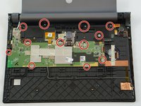
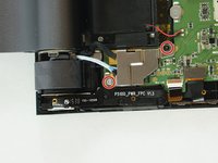
Locate the screws in the motherboard the wire cover assembly and the speakers.
-
Use the J000 screwdriver to remove the screws on the motherboard, the wire cover, and the two speakers.
-
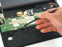
Disconnect the wifi connector on the motherboard.
-
-
-
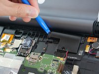
Use the spudger to lift the two speakers up from the small adhesive strip.
-
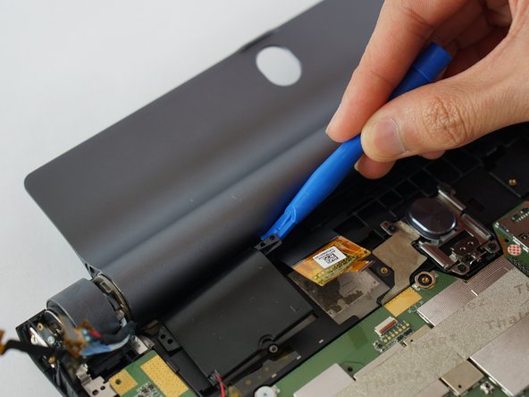
Place the spudger in the upper left corner of the motherboard and lift it to separate it from the adhesive strip under it.
-
Lift away the motherboard.
Be sure to disconnect all the ribbon cables from the mainboard before lifting it out.
-


To reassemble your device, follow these instructions in reverse order.
To reassemble your device, follow these instructions in reverse order.
crwdns2935221:0crwdne2935221:0
crwdns2935229:015crwdne2935229:0
crwdns2915084:0crwdne2915084:0

USF Tampa, Team S3-G2, Sullivan Spring 2017 crwdns2935289:0USF Tampa, Team S3-G2, Sullivan Spring 2017crwdne2935289:0
USFT-SULLIVAN-S17S3G2
crwdns2931471:04crwdne2931471:0
crwdns2935297:018crwdne2935297:0
crwdns2947410:01crwdne2947410:0
Dear @phanudej ,
I liked your post. I’d have a remark and a question. I made a mistake during the maintanance; with wich I killed a part of the MOBO. So dear users my advice if you want to connect the LCD connector remove the battery before… I had never this issue but now happened. (the device was switched off)
Could you please take a photo of the powerstage of the LCD (I think it should be that) So between the inductor (100; 10uH coil) and an capacity there is a component I do not know what is it (it smoked away) I assume it is a diode…?! They are in the white rectangle near the LCD connector
Thanks in advance
Best regards