crwdns2915892:0crwdne2915892:0
If you experience hardware failure with the webcam of your Lenovo ThinkPad T480, you may want to replace it. This guide gives you the step by step instructions to remove the camera assembly.
It’s important to do a little troubleshooting prior to the repair to determine if your webcam issue is a hardware failure. The guide on the Lenovo support page will walk you through potential software issues that might be the cause of your problems.
Prior to beginning the repair, disable the internal battery, power off your device, and unplug the charging cable.
crwdns2942213:0crwdne2942213:0
-
-
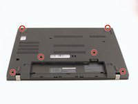
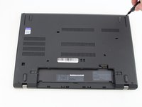
Flip the laptop over so the bottom of the device is showing.
-
-
-
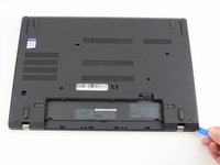
Using your fingers, slide the lock on each side of the battery to the unlocked position.
-
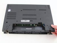
Remove the battery from the slot.
-
-
-
Use the Phillips #1 screwdriver to loosen the two screws parallel to the battery compartment.
-
-
-
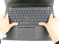
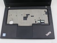
Open the laptop so the keyboard is facing you.
-
-
-
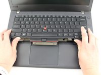
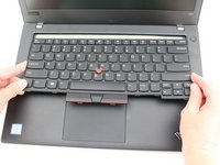
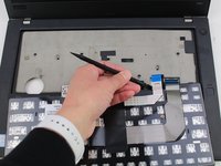
Push the keyboard towards the screen and away from the trackpad and then slide it out towards you gently.
-
-
-
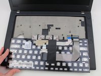
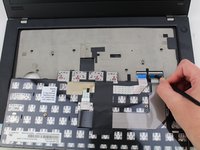
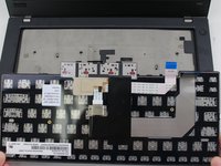
Flip the keyboard over towards you to expose the backside of the keyboard and the two ribbon connectors.
-
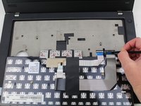
Using the black nylon spudger, flip the first ribbon connector lock open. Slide the first connector out.
-
-
-
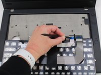
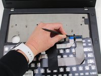
Using the black nylon spudger, unlock the second ribbon connector and slide it out from the port.
-
-
-
Using the Phillips #1 screwdriver, loosen the six captive screws.
-
-
-
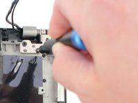
Insert the blue plastic opening tool into the space between the lower case and the chassis.
-
Slide the opening tool around the perimeter of the case to release the clips holding the case and the chassis together.
-
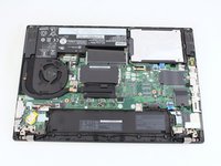
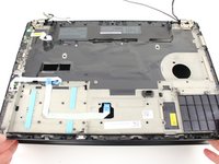
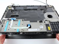
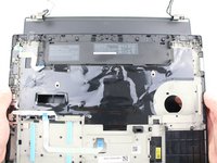
Remove the back case.
-
-
-
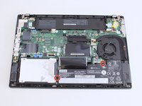
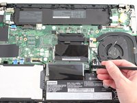
Use a Phillips #1 screwdriver to remove the two 4.6 mm screws that secure the internal battery to the frame.
-
-
-
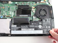
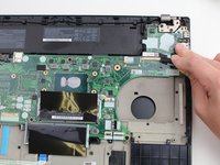
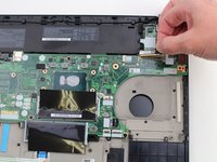
Use the spudger to slide the battery socket connector parallel to the motherboard and out of its socket on the motherboard.
-
-
-
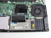
Lift the battery straight out of its recess and remove it.
-
-
-
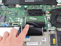
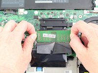
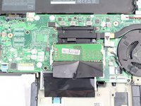
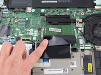
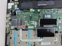
Pull the black plastic sheet back to reveal the RAM stick.
-
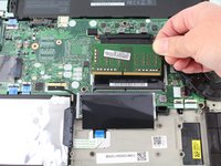
Using your fingers, pull the metal arms (located on both sides of the RAM stick) slightly away from it .
-
-
-
-
Slide the RAM stick out from the memory module slot.
-
-
-
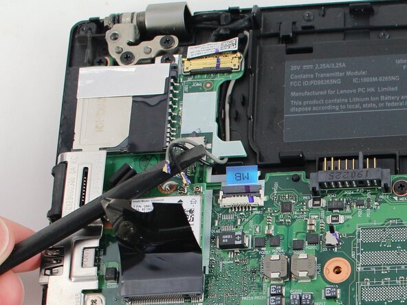
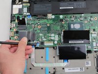
Using the Phillips #1 screwdriver, remove the single 3.6 mm screw at the top of the Wi-Fi card attaching it to the motherboard.
-
-
-
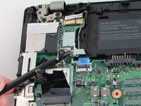
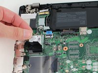
Slide a thin, ESD-safe pry tool or angled tweezers under the metal neck of the connector (as close to the head as possible) and lift straight up from the board.
-
-
-
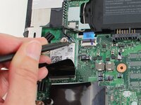
Slide the Wi-Fi card out from the slot to remove it from the board.
-
-
-
Using an IC extractor or black nylon spudger, unplug the connector from the socket on the motherboard.
-
-
-
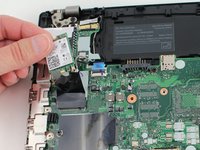
Using the black nylon spudger, pry the coin cell battery off of the motherboard.
-
-
-
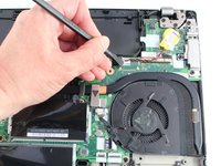
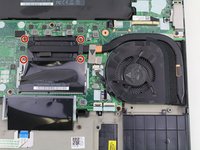
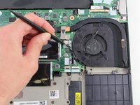
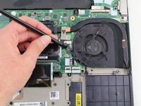
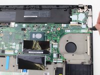
Using the Phillips #1 screwdriver, loosen the four captive screws in the arm of the heatsink.
-
-
-
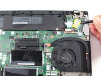
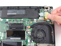
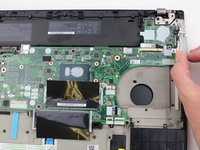
Use the black nylon spudger to slide the fan connector parallel to the motherboard and out of its socket on the motherboard.
-
-
-
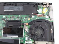
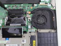
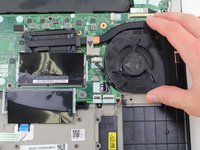
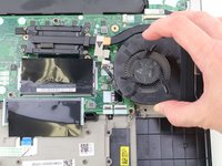
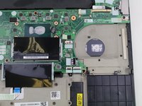
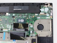
Lift the fan assembly off of the board.
-
-
-
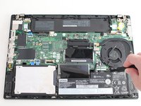
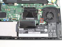
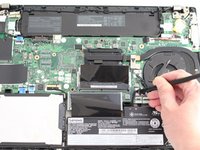
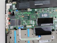
Using the black nylon spudger, lift the connector lock up.
-
Disconnect the storage cable from the system board.
-
-
-
Lift the hard drive up with a tab if it has one or with your spudger.
-
Lift the drive assembly from the system.
-
-
-
Using the Phillips #1 screwdriver, remove three 4.6 mm screws from the I/O bracket.
-
-
-
Lift the I/O bracket off the motherboard.
-
-
-
Using the Phillips #1 screwdriver, remove the three 4.1 mm screws from the RJ45 bracket.
-
Lift the bracket off of the motherboard.
-
-
-
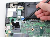
Use the black nylon spudger to lift up the small locking flap on the power button cable's ZIF connector.
-
Slide the power button cable out of the ZIF connector.
-
-
-
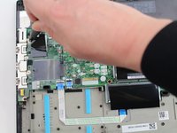
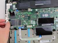
Using the black nylon spudger, disconnect the LCD cable from the motherboard.
-
-
-
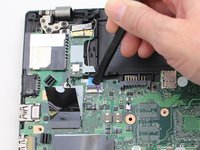
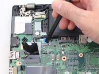
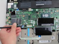
Use the tip of a spudger or an opening tool, to flip up the small, hinged locking flap on the camera cable connector to remove the cable from the motherboard.
-
-
-
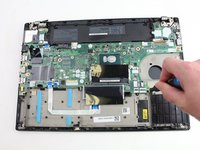
Using the black nylon spudger, remove the NFC cable connector and trackpad connector from the motherboard.
-
-
-
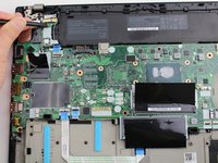
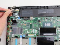
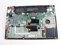
Using the Phillips #1 screwdriver, remove seven 3.6 mm screws from the motherboard.
-
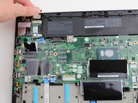
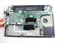
Lift the motherboard off of the case to remove it.
-
-
-
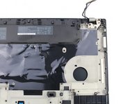
Remove the cables from the cable guides.
-
-
-
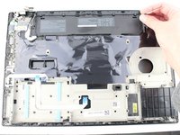
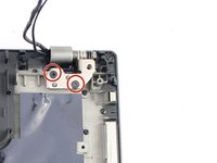
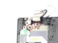
Using the Phillips #1 screwdriver, remove two 4.3 mm screws from each hinge (four total).
-
-
-
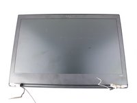
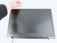
Lift the keyboard bezel up and slide it out from the hinges to separate it from the LCD assembly.
-
-
-
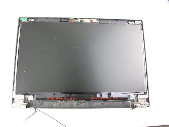
Use the metal spudger to create a space between the bezel and lid and carefully undo the clips around the perimeter of the bezel.
-
-
-
Finish removing the bezel from the screen using the metal spudger and your hands.
-
-
-
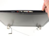
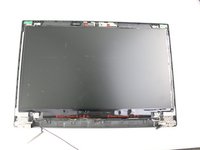
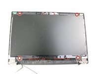
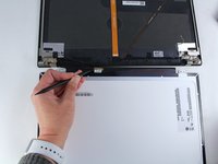
Remove the four 3.0 mm Phillips #1 screws from the four corners of the LCD screen.
-
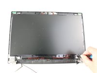
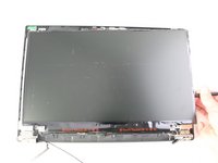
Lift it up using the spudger and flip it over gently towards you.
-
-
-
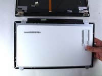
Using the black nylon spudger, disconnect the display connector cable and remove the LCD screen.
-
-
-
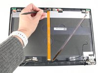
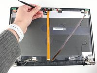
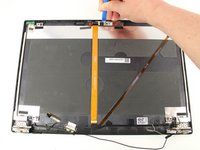
Disconnect the camera cable from the top cover using the black nylon spudger.
-
-
-
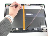
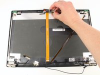
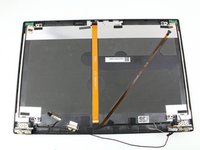
Use the opening tool to pry the camera up and lift it out.
-


To reassemble your device, follow the above steps in reverse order.
Take your e-waste to an R2 or e-Stewards certified recycler.
Repair didn’t go as planned? Try some basic troubleshooting, or ask our Answers community for help.
crwdns2935221:0crwdne2935221:0
crwdns2935229:02crwdne2935229:0

