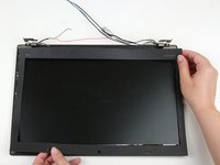
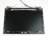
crwdns2915892:0crwdne2915892:0
Use this guide to replace the camera/microphone module cable in a Lenovo ThinkPad T460.
The built-in webcam (also called a laptop camera) in this laptop is integrated with the webcam. If you are experiencing issues with the webcam and microphone and have ruled out the camera/microphone module itself as the issue, you may need to replace your laptop’s camera/microphone module cable.
Make sure to disable the internal battery, power down your device, and disconnect from any external power sources before you begin.
crwdns2942213:0crwdne2942213:0
-
-
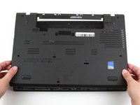
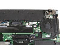
Place the laptop so that the bottom is facing upwards.
-
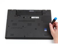
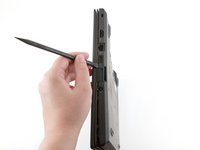
Slide the latch on the left side of the battery to the left until it clicks in place.
-
-
-
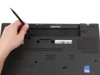
Slide the latch on the right side of the battery to the right and hold it in place with your thumb.
-
Use your other hand to slide the battery towards the back of the laptop.
-
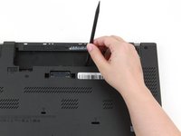
Lift the battery up and away from the laptop.
-
-
-
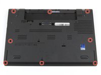
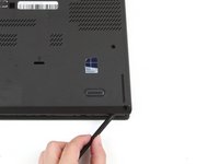
Loosen the eight captive screws in the bottom cover using a Phillips #1 screwdriver.
-
-
-
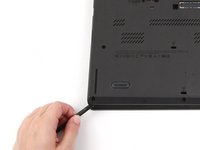
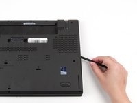
Insert the flat end of a spudger in between the bottom cover and the rest of the laptop, starting in the lower left corner.
-
Pry the lower left corner of the bottom cover up by a few millimeters.
-
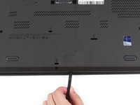
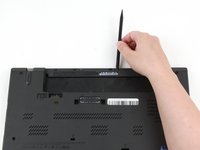
Slide the spudger along the bottom of the laptop to release the clips until you reach the lower right corner.
-
-
-
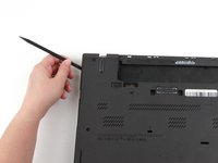
Slide the spudger along the right and top sides of the bottom cover to release the clips.
-
-
-
Use the spudger to pry the upper left corner up by a few millimeters.
-
Pry up the sections of the bottom cover with printed logos of the ports.
-
-
-
Use the spudger to pry up the bottom cover in the lower portion of the external battery compartment by a few millimeters.
-
-
-
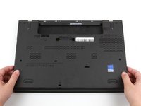
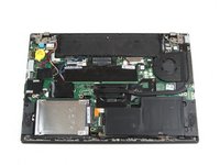
Use both hands to lift the bottom cover up and away from the laptop.
-
-
-
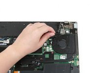
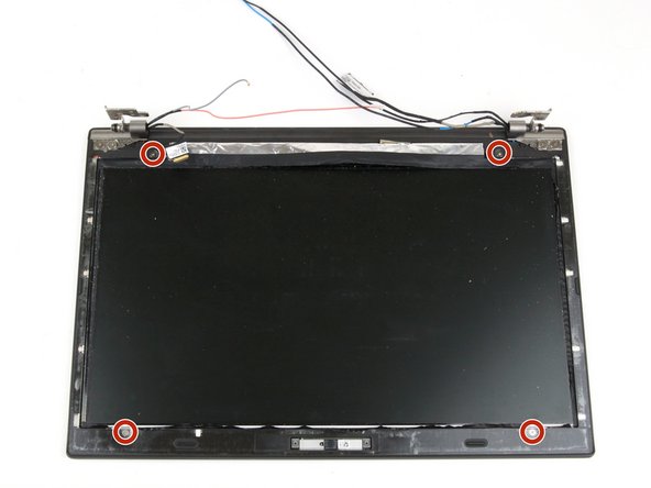
Remove the two 3.7 mm screws from the LCD cable bracket using a Phillips #1 screwdriver.
-
-
crwdns2935267:0crwdne2935267:0Tweezers$4.99
-
Use a pair of tweezers to lift the LCD cable bracket away from the motherboard.
-
-
-
Use the flat end of a spudger to disconnect the flat-topped LCD cable connector.
-
-
-
Use your fingers to remove the cable from its slots.
-
-
-
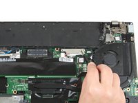
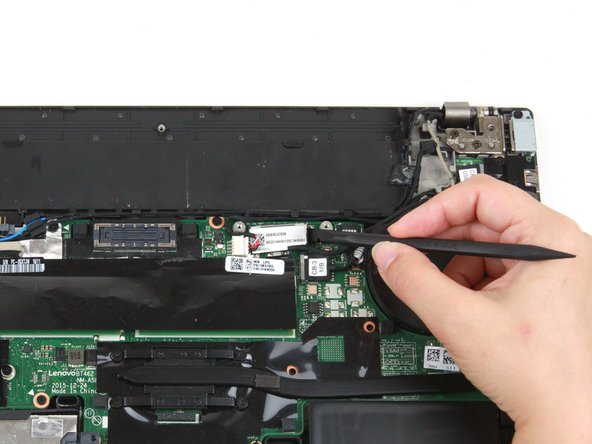
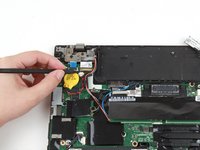
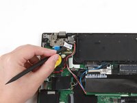
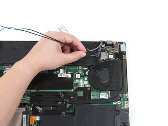
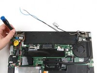
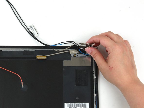
Use the pointed end of a spudger to lift up the metal clip on the camera/microphone cable.
-
-
-
-
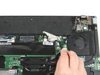
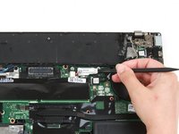
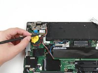
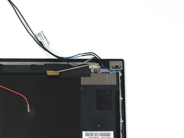
Use the flat end of a spudger to detach the camera/microphone cable connector from its socket.
-
-
-
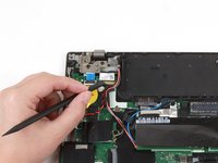
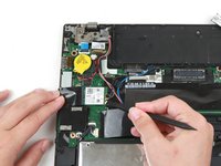
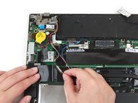
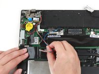
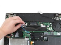
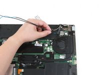
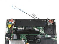
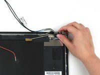
Use the flat end of a spudger to disconnect the black and gray coaxial cables from the Wi-Fi card.
-
-
-
If your laptop has a WWAN card, disconnect the red and blue coaxial cables using the flat end of a spudger.
-
If your laptop does not have a WWAN card, remove the tape holding the red and blue coaxial cables in place.
-
-
-
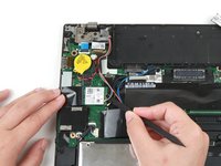
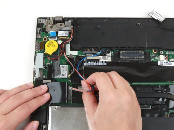
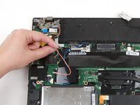
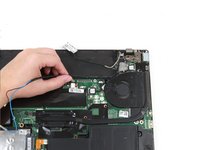
Use your fingers to remove the gray and red coaxial cables from their slots along the motherboard.
-
-
-
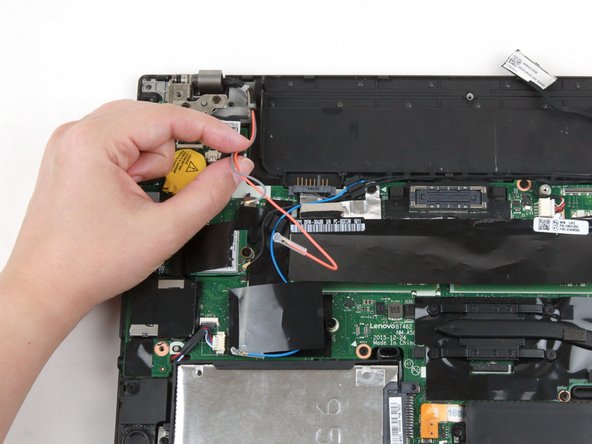
Use your fingers to remove the blue and black coaxial cables from their slots along the top of the motherboard.
-
-
-
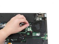
Remove the four 4.7 mm screws from the hinges using a Phillips #1 screwdriver.
-
-
-
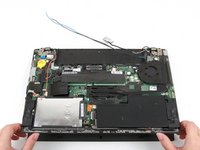
Lift the bottom of the laptop up by a few inches to rotate the two upper hinges.
-
Place the bottom of the laptop back down.
-
-
-
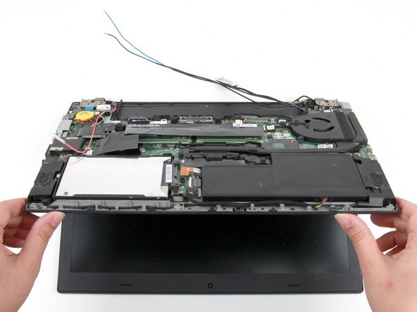
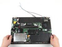
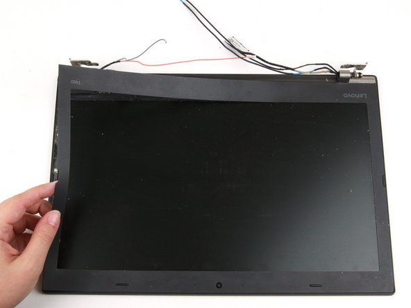
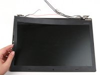
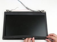
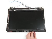
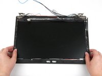
Use both of your hands to lift the bottom of the laptop away from the LCD assembly.
-
-
-
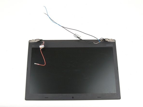
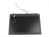
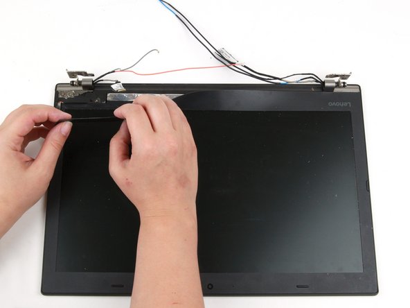
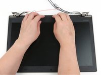
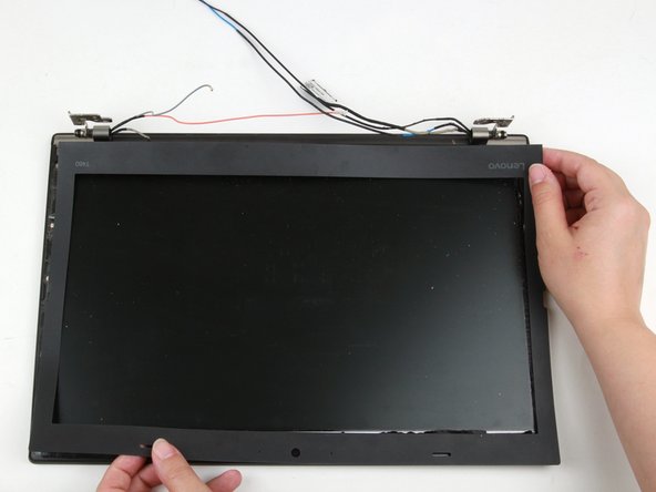
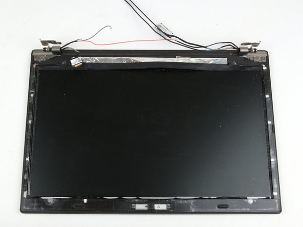
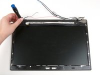
Use your hands to peel up the thin LCD bezel sheet from the rest of the display, starting in the area between the hinges.
-
Use your hands to continue peeling the bezel sheet away from the left side of the laptop.
-
-
-
Use your hands to continue peeling the bezel sheet away from the bottom and right sides of the laptop.
-
Use both hands to lift the LCD bezel sheet up and away from the laptop.
-
-
-
Remove four 3.3 mm screws from the LCD bezel using a Phillips #1 screwdriver.
-
-
-
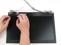
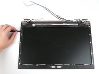
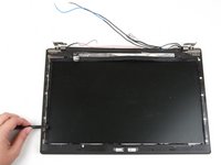
Use the flat end of a spudger to create a gap between the bezel and the display, starting in the upper left corner.
-
Continue to use the spudger around the left side, bottom, and right side of the laptop to detach the clips securing the bezel to the display.
-
-
-
Use both hands to lift the bezel up and away from the display assembly.
-
-
-
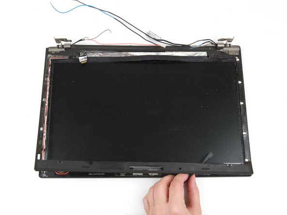
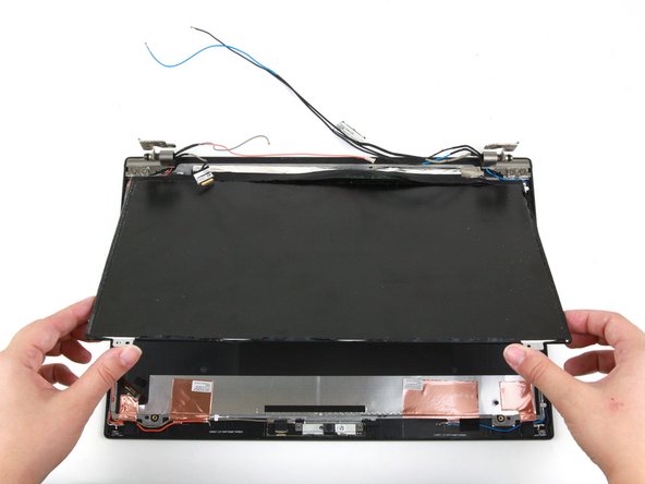
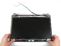
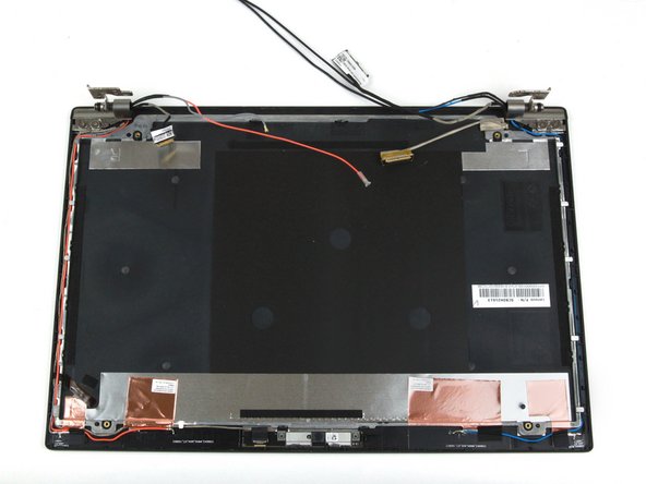
Use both hands to lift the bottom corners of the display panel
-
Gently flip the display panel over.
-
-
-
Use the pointed end of a spudger to flip up the metal bar securing the connector.
-
-
-
Use the flat end of a spudger to disconnect the display cable from its socket.
-
-
-
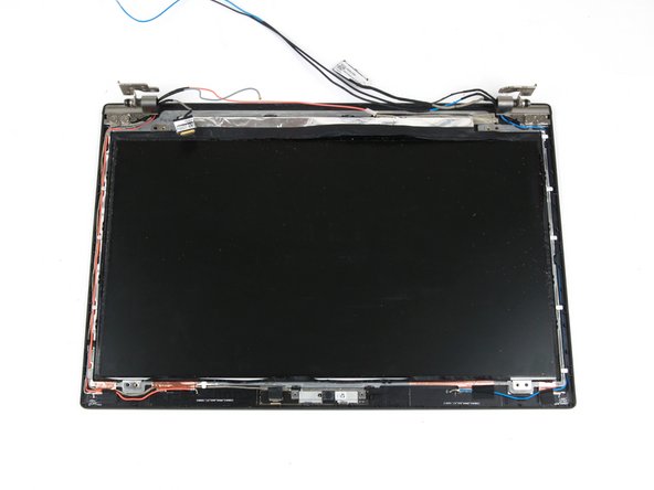
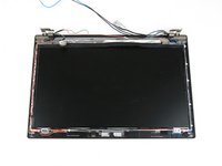
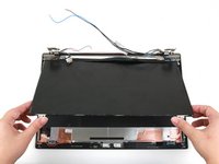
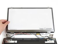
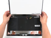
Use your hands to remove the display panel from the rest of the display assembly.
-
-
-
Remove the four 3.2 mm hinge screws using a Phillips #1 screwdriver.
-
-
-
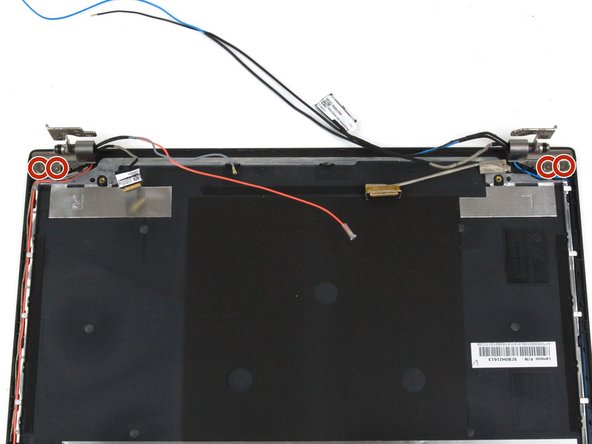
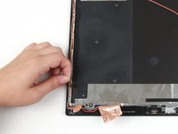
Use your fingers to lift the hinge in the upper left corner up and away from the laptop.
-
-
-
Use your fingers to lift the hinge in the upper right corner up and away from the laptop.
-
-
-
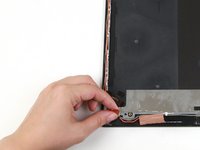
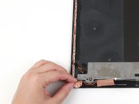
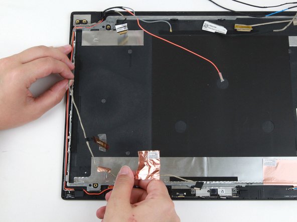
Use your fingers to peel the large copper tape up from the display assembly in the bottom left-hand corner.
-
-
-
Use your fingers to peel the small copper tape up from the display assembly in the bottom left-hand corner.
-
-
-
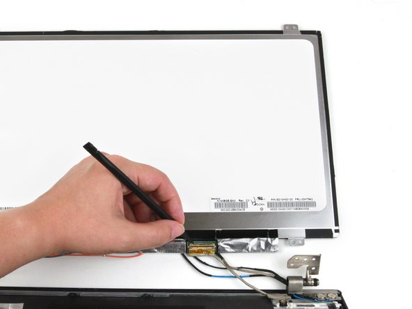
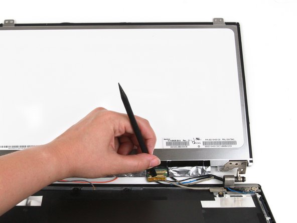
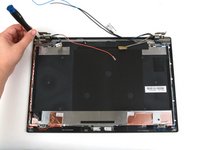
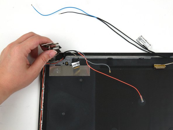
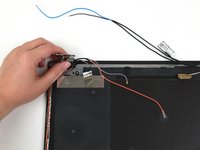
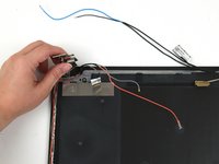
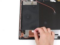
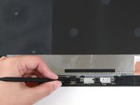
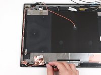
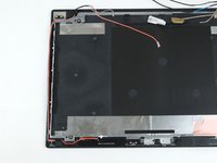
Use the flat end of a spudger to disconnect the cable from the camera/microphone module.
-
-
-
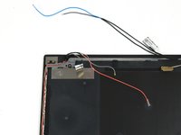
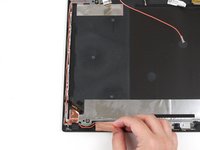
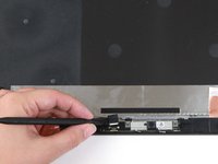
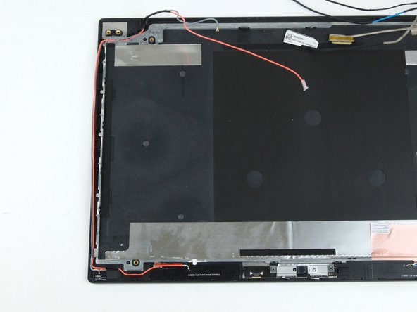
Use your fingers to peel up the orange cable from the laptop.
-
-
-
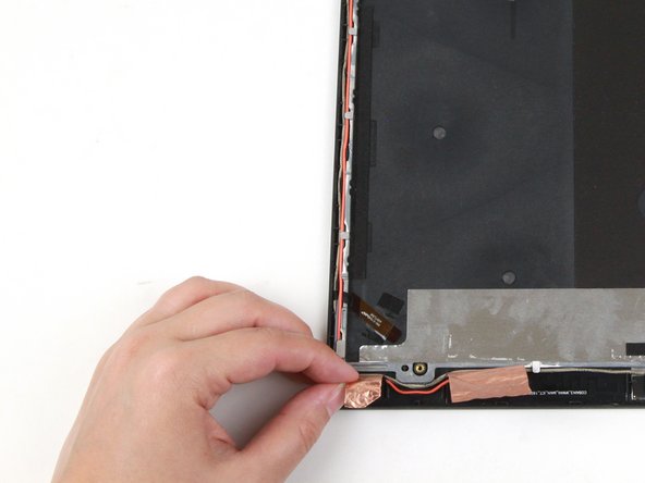
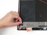
Use one hand to lift up the gray cable from the laptop.
-
Use your other hand to remove the gray wire from its slots along the left side of the display assembly.
-


To reassemble your device, follow these instructions in reverse order.
Take your e-waste to an R2 or e-Stewards certified recycler.
Repair didn’t go as planned? Try some basic troubleshooting, or ask our Answers community for help.