crwdns2915892:0crwdne2915892:0
If your Lenovo IdeaPad 3-15IML05 will no longer power on or is failing, use this guide to replace your motherboard.
Before beginning this guide, attempt other possible solutions, this should be a last resort. Refer to the device’s troubleshooting page for additional diagnostic assistance.
The motherboard is a critical component of your computer, it allows internal components to communicate with one another. Motherboards primarily fail due to electrical surges, overheating, and physical damage. Replacing the motherboard can extend your computer's lifespan and reduce e-waste.
During this repair, all components and cables connected to the motherboard must be disconnected. Take your time and proceed through each step carefully to lower the risk of additional damage.
Working with lithium-ion batteries can be hazardous. A connected or swollen battery may catch fire if damaged. Before beginning this repair, discharge the battery below 25%, power off the laptop, and unplug all peripherals.
If you encounter a swollen battery, refer to this guide for disposal.
crwdns2942213:0crwdne2942213:0
-
-
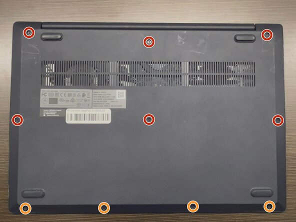
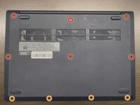
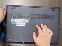
Use a Phillips #1 screwdriver to remove the following screws:
-
Six 7 mm screws
-
Four 4 mm screws
-
-
-
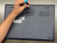
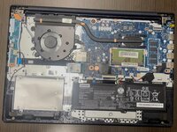
Insert an opening pick into the seam between the lower case and chassis.
-
Slide the pick around the entire perimeter until all of the plastic retaining clips release.
-
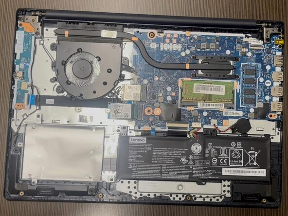
Remove the lower case.
-
-
-
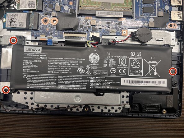
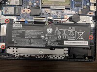
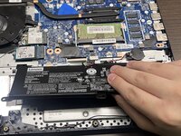
Use a Phillips #00 screwdriver to remove the three 5 mm screws securing the battery.
-
To remove the battery, slide it to the right and lift it away from the hard drive cover.
-
-
-
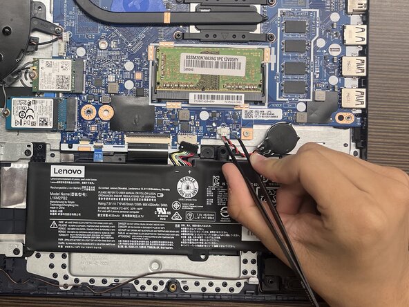
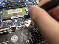
Using a spudger or tweezers, push the CMOS battery JST connector out of its socket.
-
-
-
Grasp and remove the CMOS battery, which is secured with adhesive.
-
-
-
-
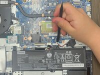
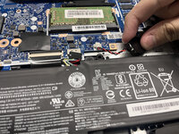
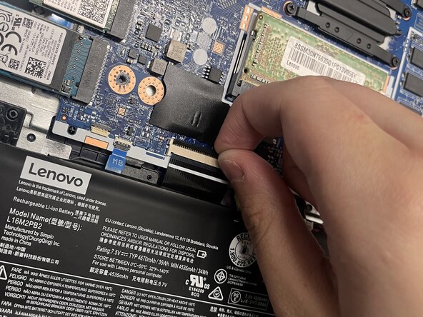
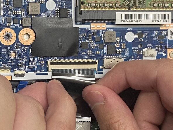
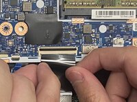
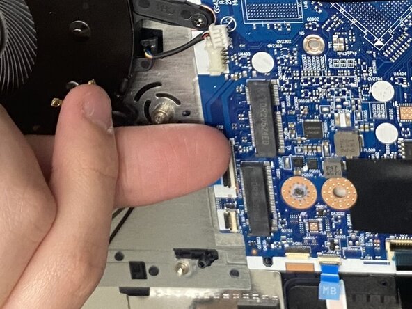
Use your fingernails to flip up the two locking flaps on the ZIF connectors near the battery.
-
-
-
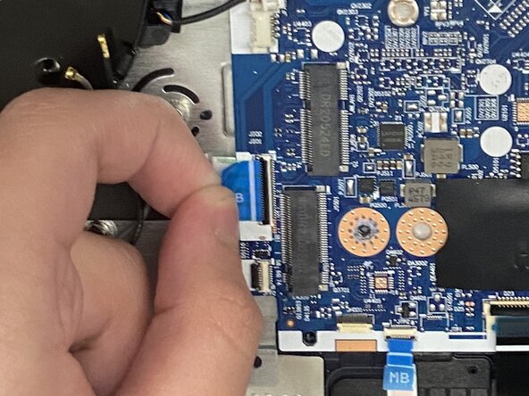
For the larger ZIF cable, grab the sides and gently pull it out of its socket.
-
For the smaller ZIF cable, use the blue pull tab provided and gently pull it out of its socket.
-
-
-
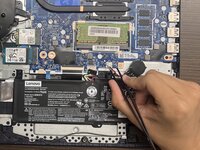
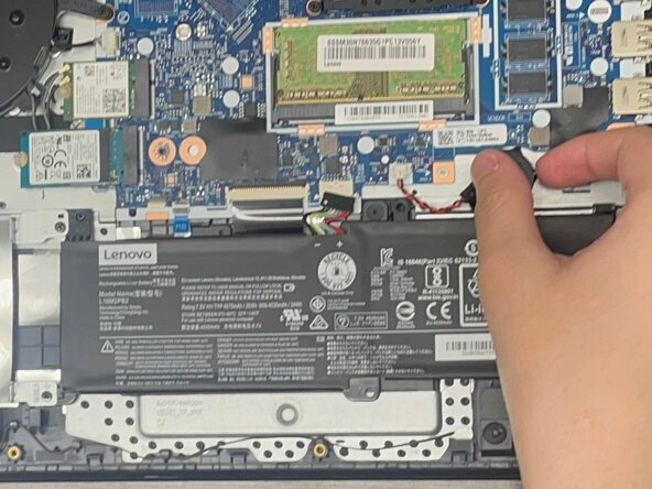
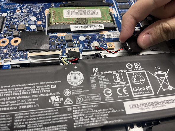
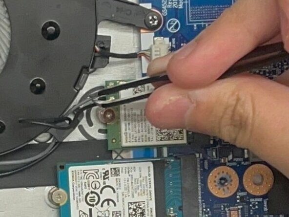
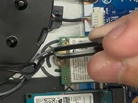
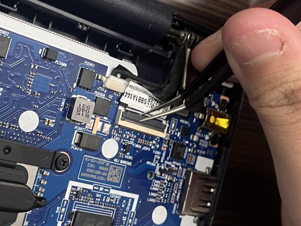
Using angled tweezers, slide them under the metal neck of the antenna cables, and lift straight up.
-
-
-
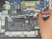
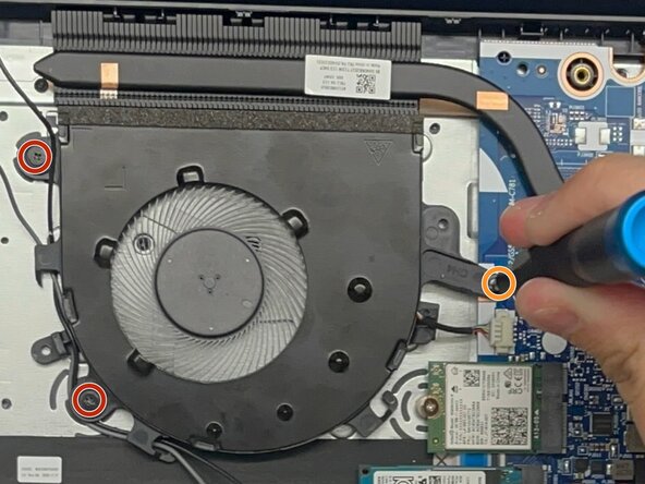
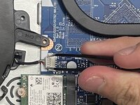
Using tweezers, gently pull the JST fan cable out of its socket.
-
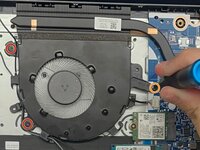
Use a Phillips #00 screwdriver to remove the following screws:
-
Two 3.5 mm screws
-
One 5 mm screw
-
Lift the fan and guide the antenna cables out of the clips on its edge.
-
Slightly shift the fan to the left, away from the motherboard.
-
-
-
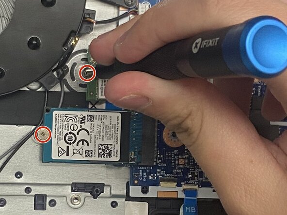
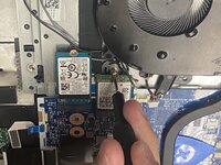
Using a Phillips #0 screwdriver remove each of the two 2.5 mm screws that secure the SSD and Wi-Fi card.
-
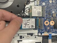
Pull the SSD and Wi-Fi card out of their sockets.
-
-
-
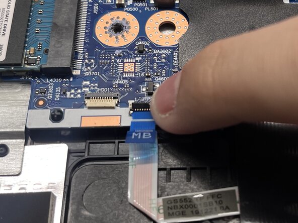
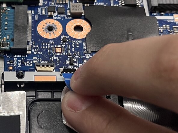
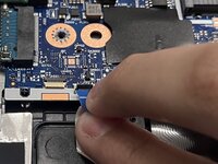
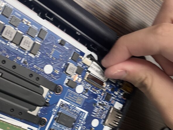
Using your fingernails, flip up the locking flap on the ZIF cable connector, located near the fan and motherboard
-
Use the blue pull tab provided and gently slide the cable out of its socket.
-
-
-
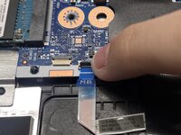
Using angled tweezers, flip up the locking flap on the ZIF cable connector.
-
For the ZIF cable, grab the sides and gently pull it out of its socket.
-
Using tweezers, gently pull the JST cable out of its socket.
-
-
-
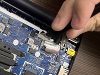
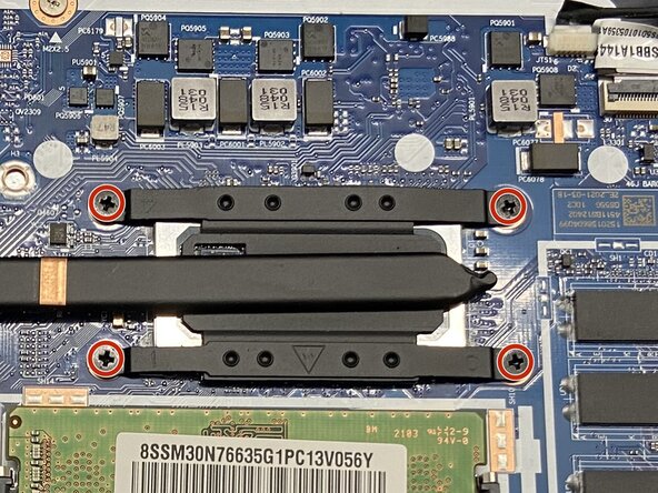
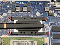
Use a Phillips #00 screwdriver to remove the four 2.5 mm screws that secure the heat sink.
-
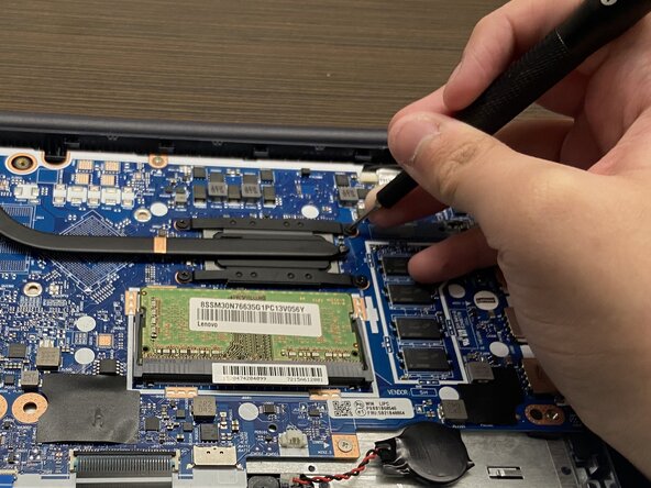
Lift the heat sink straight up.
-
-
-
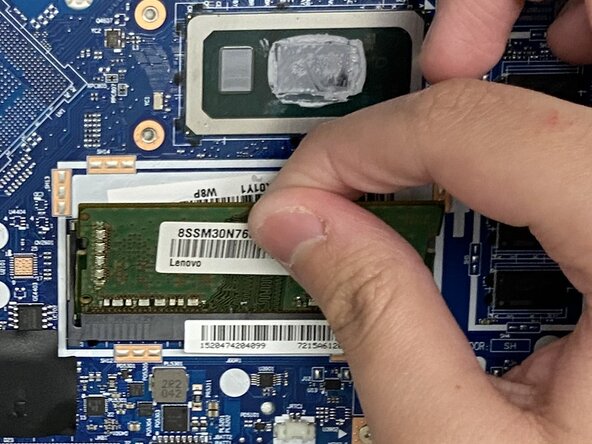
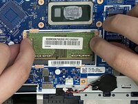
Push both of the metal arms away from the RAM module.
-
Pull the RAM out of its socket.
-
-
-
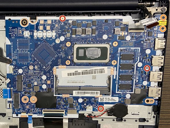
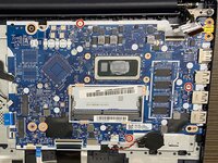
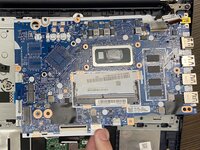
Use a Phillips #00 screwdriver to remove the following screws:
-
Three 2.5mm screws
-
Two 3.5mm screws
-
Lift and pull the motherboard away.
-


To reassemble your device, follow the above steps in reverse order.
Take your e-waste to an R2 or e-Stewards certified recycler.
Repair didn’t go as planned? Try some basic troubleshooting or ask our Answers community for help.

crwdns2935287:0crwdne2935287:0

Austin Community College, Team 22-1, Watkins Summer 2025 crwdns2935289:0Austin Community College, Team 22-1, Watkins Summer 2025crwdne2935289:0
AUSTINCC-WATKINS-SU25S22G1
crwdns2931471:03crwdne2931471:0
crwdns2935297:07crwdne2935297:0