crwdns2915892:0crwdne2915892:0
Follow this guide to replace a damaged or drifting joystick in the left Joy-Con 2 controller. If you need to replace the joystick in a right Joy-Con 2, follow this guide instead.
The Joy-Con 2 uses JIS screws. If you use a non-iFixit Phillips driver in JIS screws, you'll risk stripping them.
crwdns2942213:0crwdne2942213:0
-
-
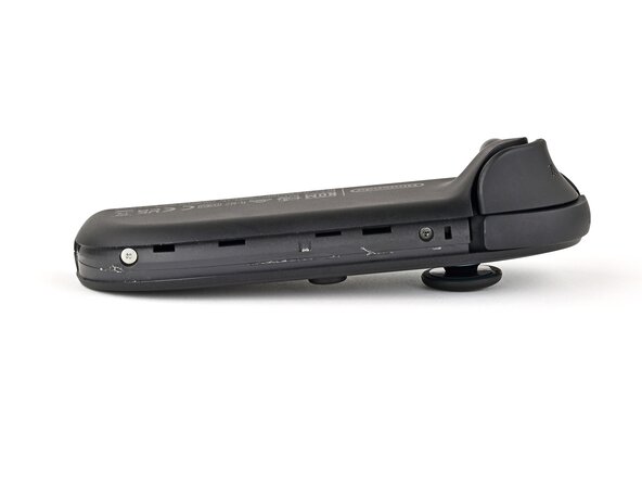
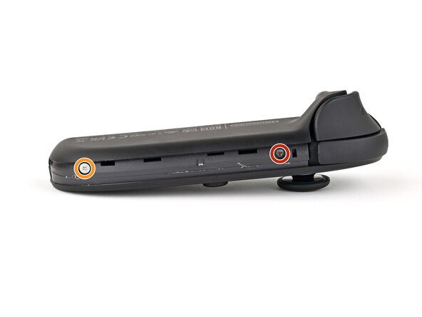
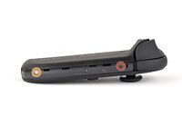
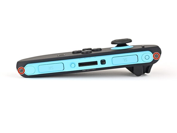
Use a tri‑point Y00 driver to remove the two 3.1 mm‑long black screws on the right edge of the controller.
-
-
-
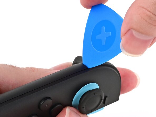
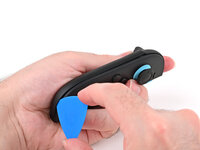
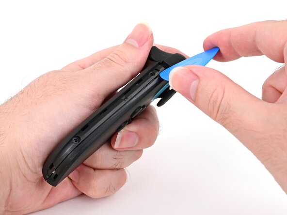
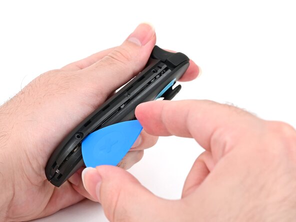
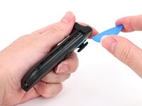
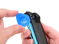
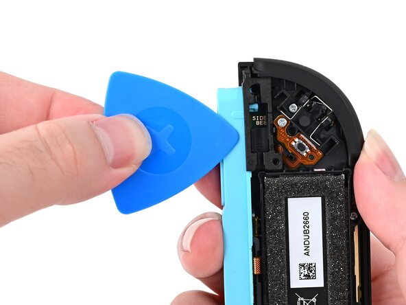
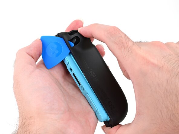
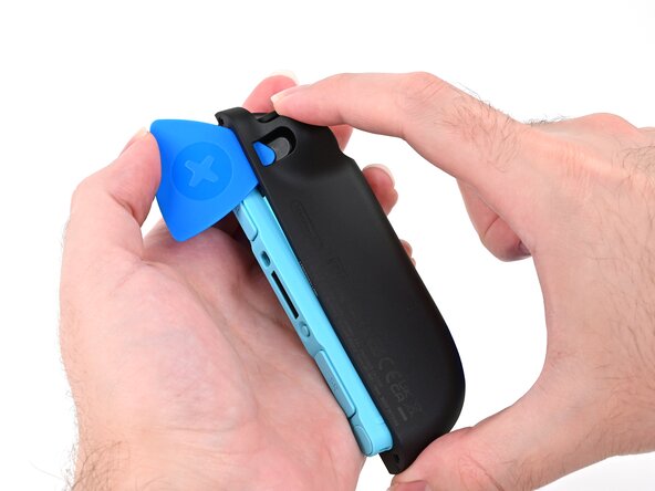
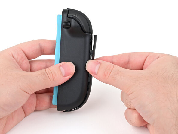
Insert an opening pick into the gap underneath the bumper button on the left side of the controller, with a point of the pick pointing downwards.
-
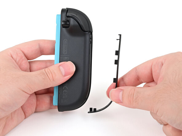
Pry up to slightly lift the plastic strip running across the left edge of the controller.
-
-
-
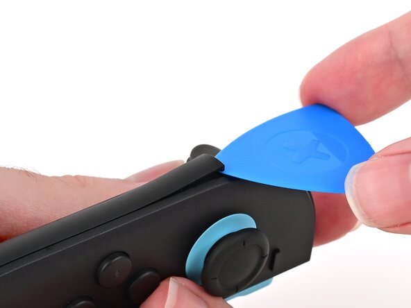
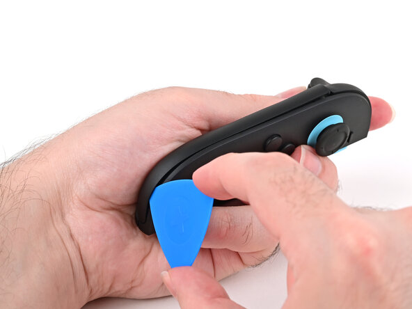
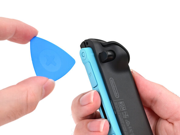
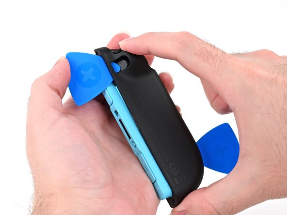
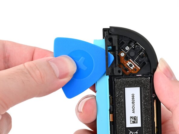
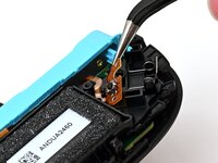
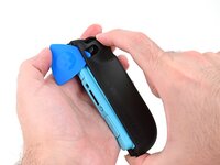
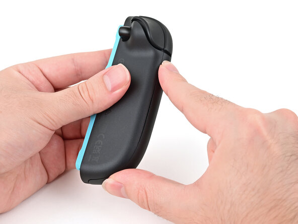
Slide the opening pick around to the front of the controller.
-
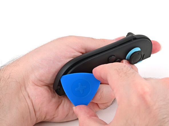
Slide the opening pick down the plastic strip to separate the clips and adhesive securing it to the controller's body.
-
-
-
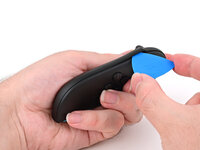
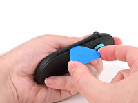
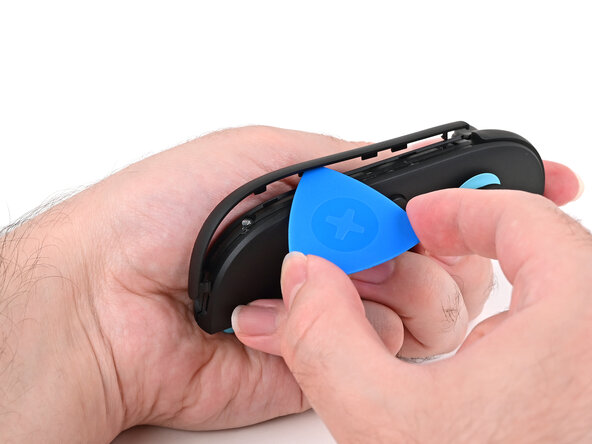
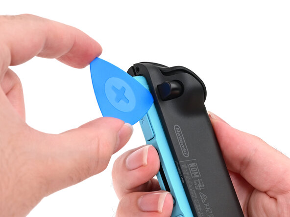
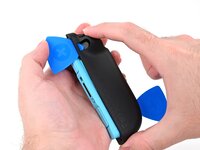
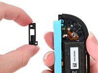
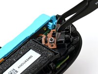
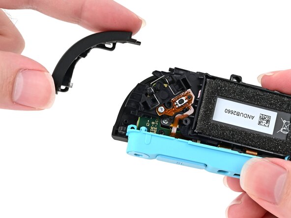
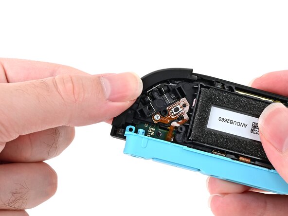
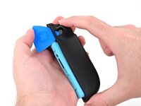
Pry up on the bottom edge of the plastic strip with slow, steady force.
-
Repeat this prying action along the length of the strip until it's fully detached.
-
-
-
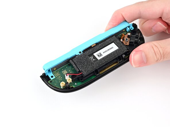
Remove the two screws on the left edge of the controller:
-
One 3.1 mm‑long tri‑point Y00 black screw
-
One 3.0 mm‑long JIS 00 silver screw
-
-
-
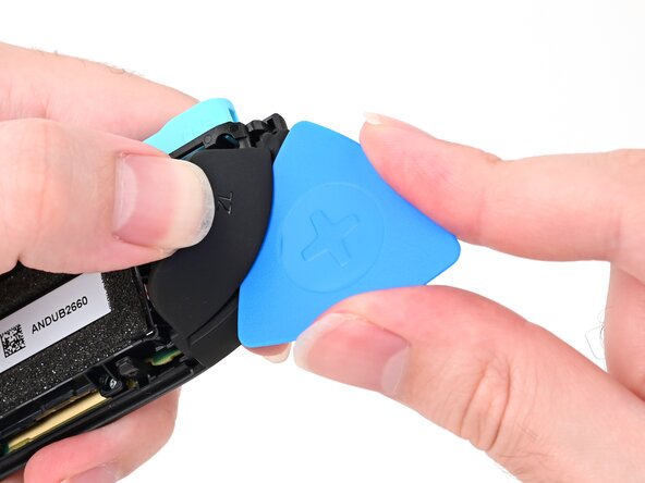
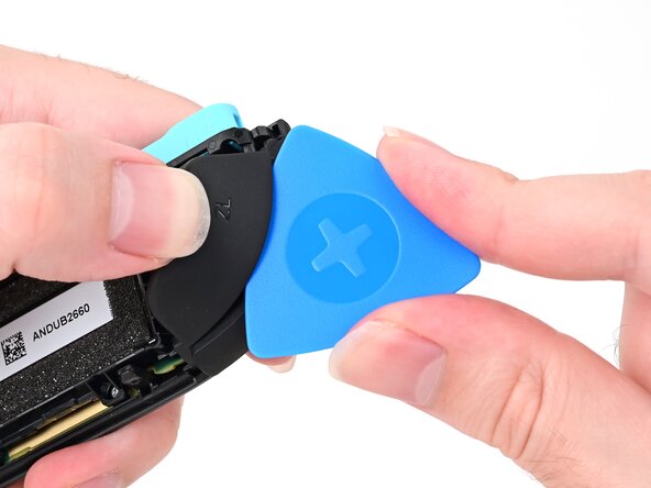
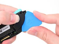
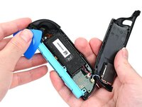
Insert an opening pick into the gap between the front and back halves of the controller on its left side.
-
Slide the pick down the controller to disengage the clips.
-
Leave the opening pick at the bottom of the controller's left edge, just before its curve.
-
-
-
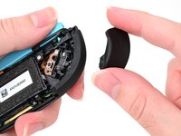
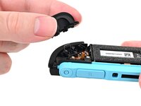
Hold the controller upside-down.
-
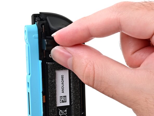
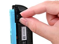
Insert a point of another opening pick next to the release button at the top of the controller.
-
Use the opening pick to press the release button through the gap.
-
-
-
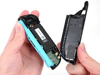
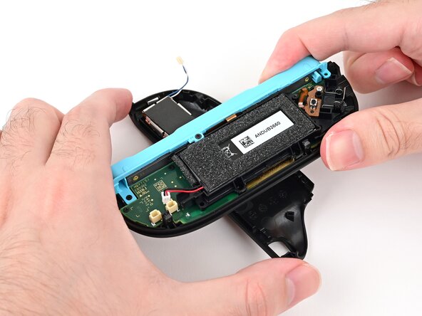
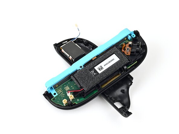
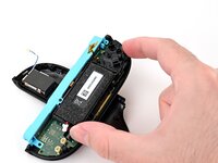
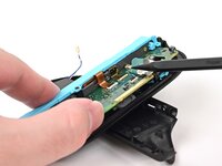
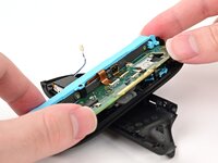
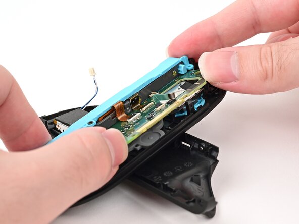
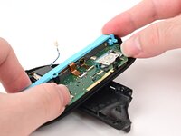
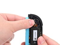
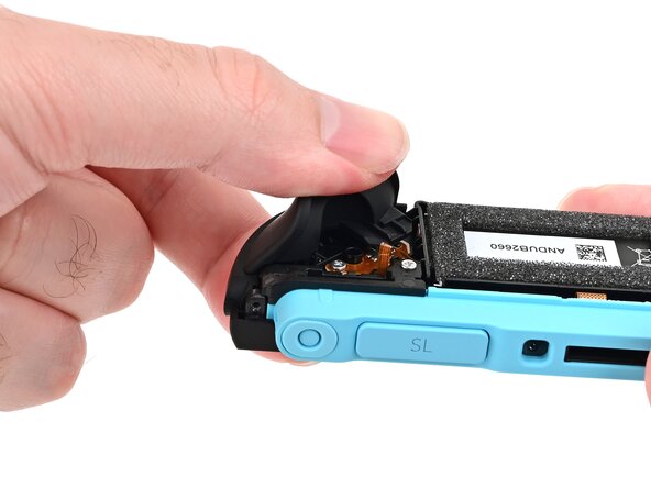
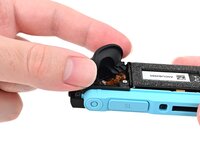
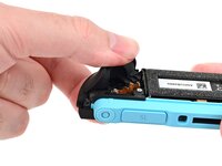
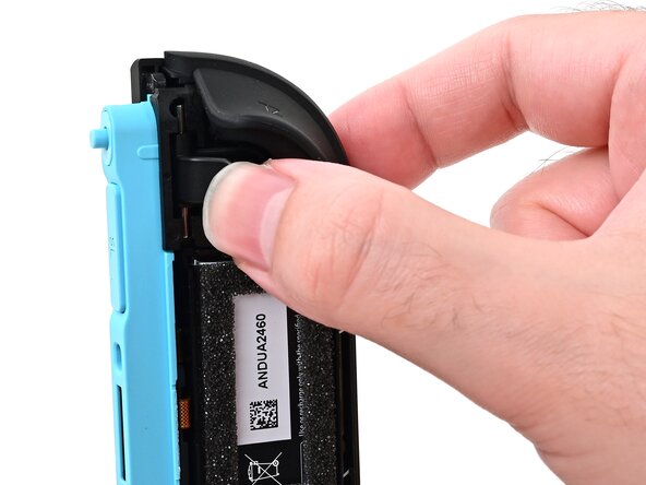
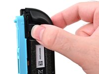
While holding the release button with the opening pick, use your other hand to slide the back cover down to release the clips securing it to the controller's body.
-
Open the back cover.
-
-
-
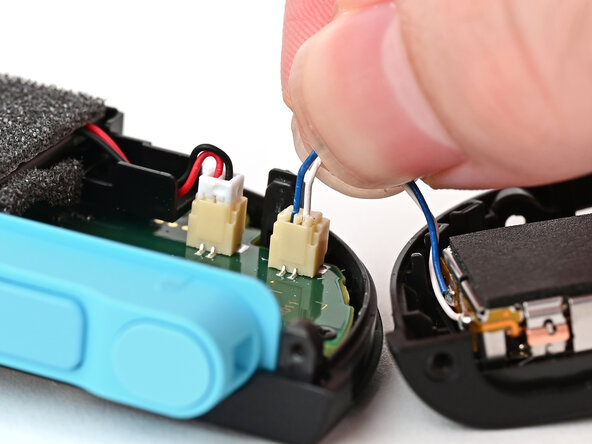
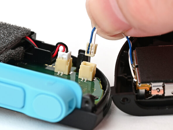
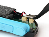
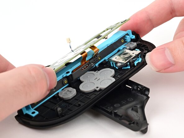
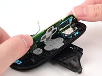
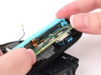
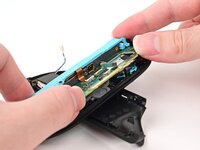
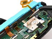
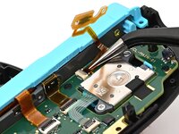
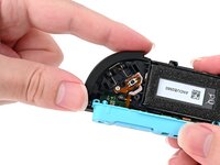
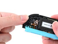
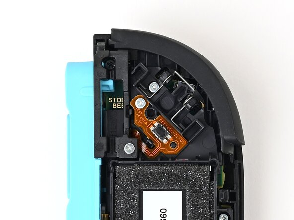
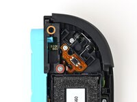
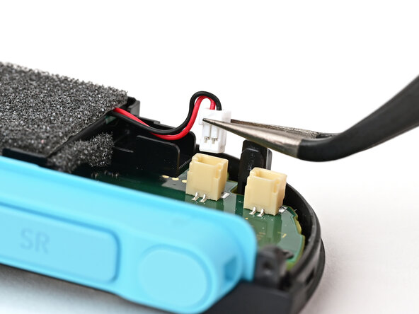
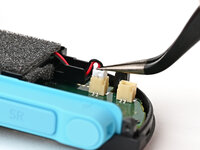
Firmly grasp the two wires (blue and white) above the rumble motor connector, located at the bottom of the controller's board, and pull the beige connector out of its socket.
-
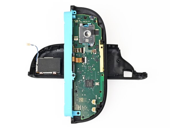
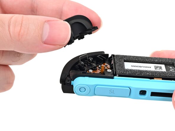
Remove the back cover.
-
-
-
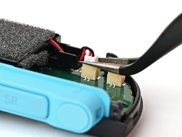
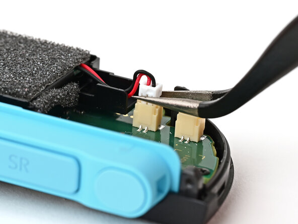
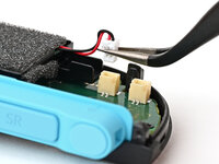
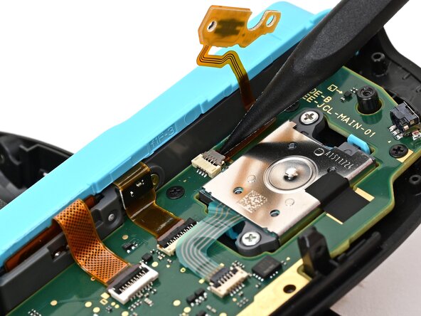
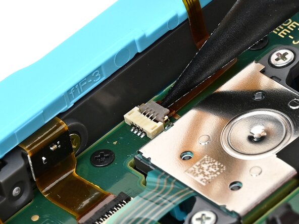
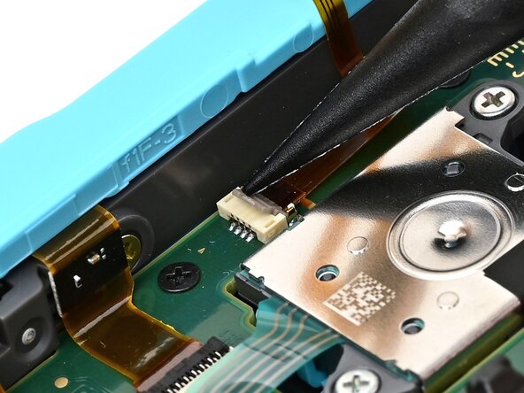
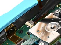
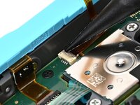
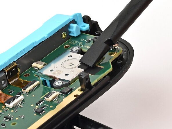
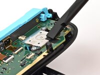
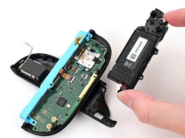
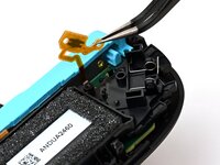
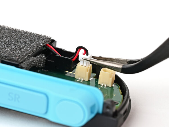
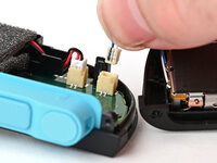
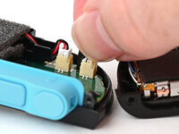
Use tweezers or your fingers to firmly grip the white JST connector and pull straight away from its socket to disconnect it.
-
-
-
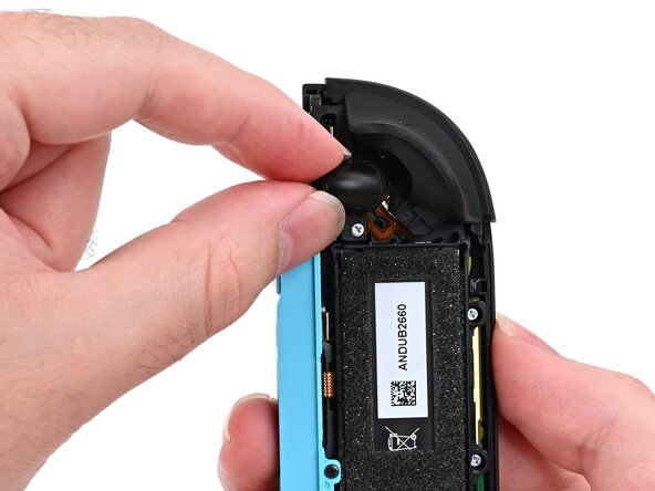
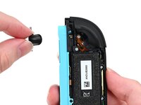
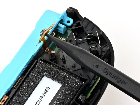
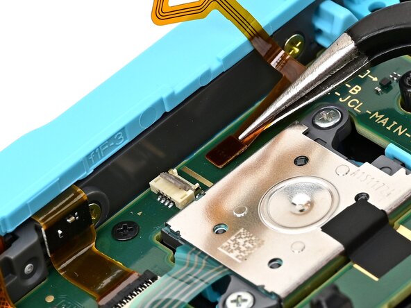
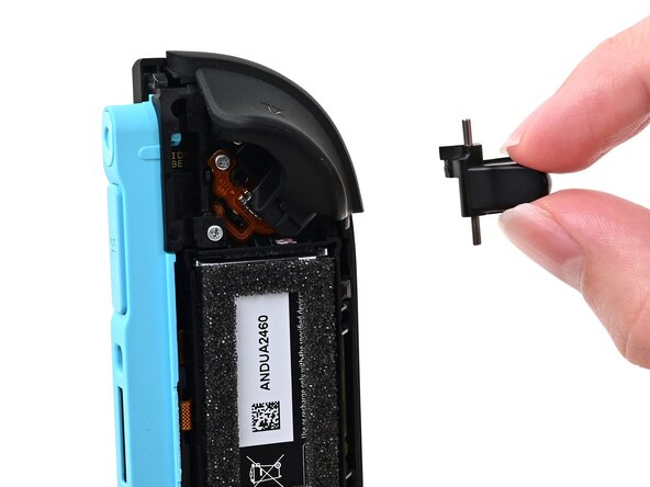
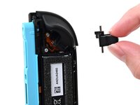
Pick up the release button and remove it.
-
-
-
Insert an opening pick into the gap between the bumper (L) and trigger (ZL) buttons at the top of the controller.
-
Pry up on the ZL button to pop it off and remove it.
-
-
-
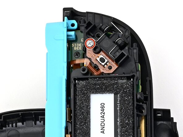
Use a JIS 00 driver to remove the two screws securing the release button mounting bracket:
-
One 3.9 mm‑long silver screw
-
One 6.2 mm‑long black screw
-
-
-
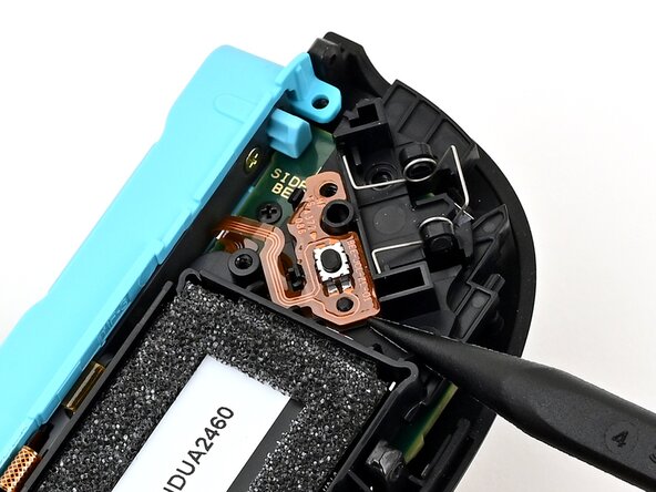
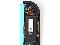
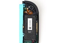
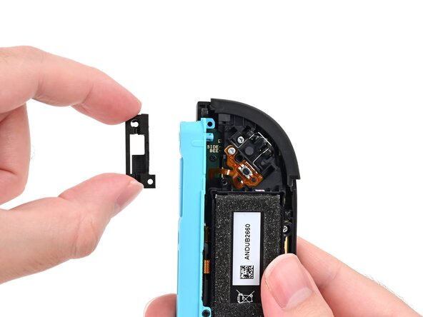
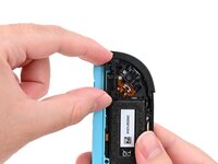
Insert an opening pick underneath the release button bracket.
-
Pry it away from the controller to remove it.
-
-
-
Use a JIS 00 driver to remove the three 3.9 mm‑long silver screws securing the midframe.
-
-
-
Hold the midframe lightly in place.
-
Pull the L bumper button off its mounting pegs and remove it.
-
-
-
Use the back cover to prop up the controller while you work.
-
-
-
Use a JIS 00 driver to remove the 3.9 mm‑long silver screw securing the trigger button board.
-
-
-
-
Insert the point of a spudger underneath the board, and lift it until it pops up.
-
-
-
Pick up and remove the midframe.
-
-
-
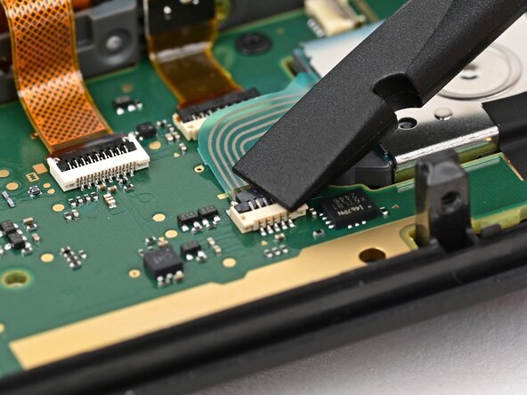
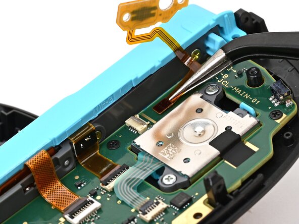
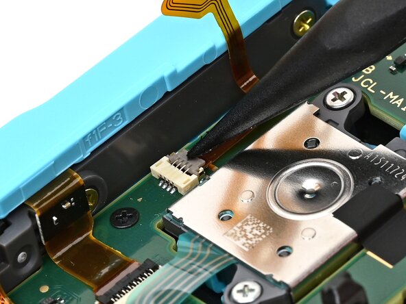
Use the point of a spudger to flip up the locking flap on the trigger button ZIF connector, located on the controller's board.
-
-
-
Use tweezers or your fingers to gently pull the cable out of its socket.
-
Remove the trigger button board.
-
-
-
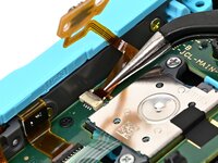
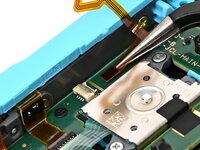
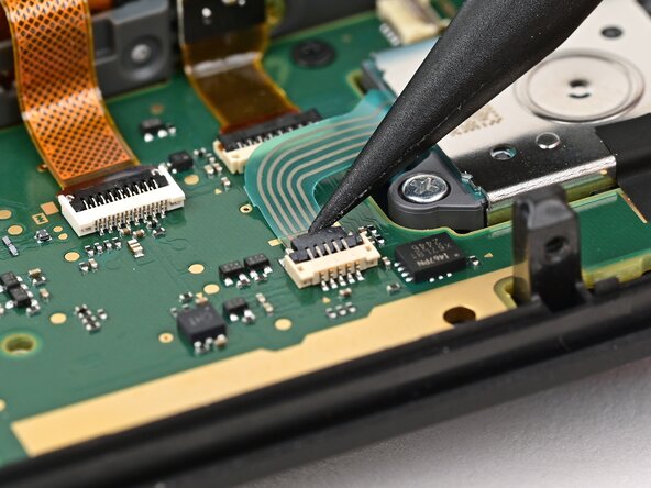
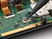
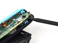
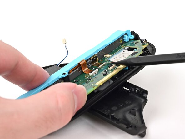
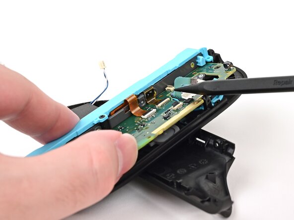
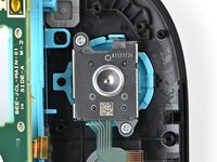
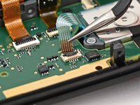
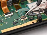
Use the point of a spudger to flip up the locking flap on the joystick cable ZIF connector, located in the center of the board.
-
-
-
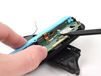
Use tweezers or your fingers to grab the brown part of the cable and gently pull the cable out of its socket.
-
-
-
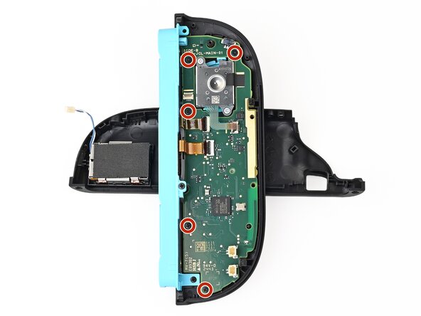
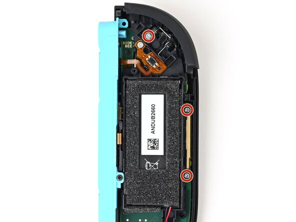
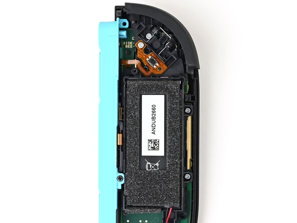
Use a JIS 00 driver to remove the five 3.1 mm‑long black screws securing the board to the controller.
-
-
-
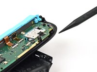
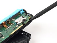
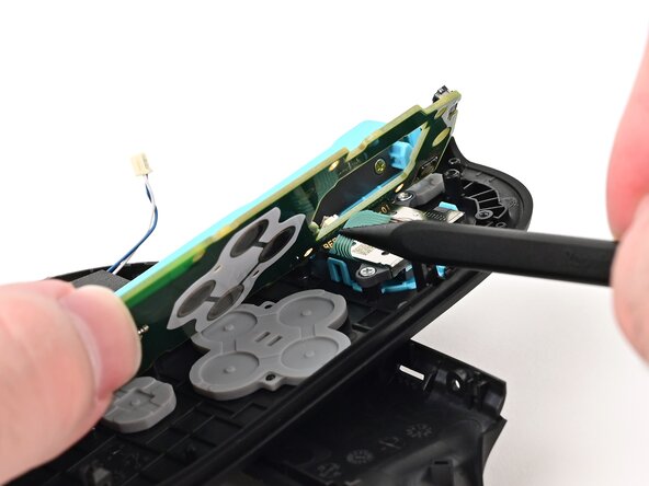
Insert the point of a spudger underneath the board, next to the joystick, between the board and the frame.
-
Pry up slowly on the board to lift it until you can grab it with your fingers.
-
-
-
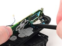
Use your fingers or a spudger to lift the joystick cable up so it's perpendicular to the joystick module.
-
-
-
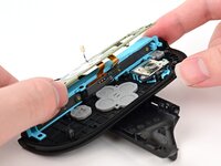
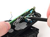
Lift the board and flip it over the controller's inner edge.
-
-
-
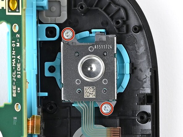
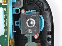
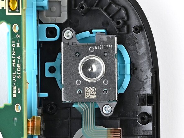
Use a JIS 00 driver to remove the two 3.9 mm‑long silver screws securing the joystick.
-
-
-
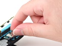
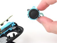
Use tweezers or your fingers to pick up and remove the joystick.
-
-
-
Congratulations on completing disassembly! The remaining steps will show how to reassemble your console.
-
-
-
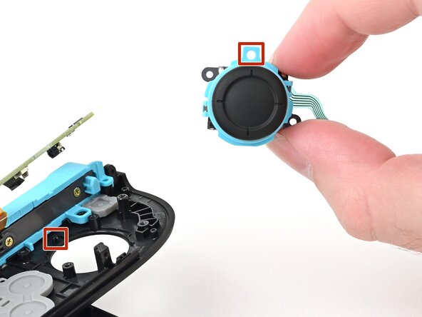
Align the circular cut-out in the joystick's frame with the peg near the controller's inner edge.
-
Set the joystick in the controller. Gently wiggle the joystick to ensure it's fully seated.
-
-
-
Use a JIS 00 driver to install the two 3.9 mm‑long silver screws securing the joystick.
-
-
-
Lower the board into the controller at an angle so it sits underneath the locking tab on the controller's inner edge.
-
Use a spudger to bend the joystick's ribbon cable so it's perpendicular with the joystick.
-
Lower the board so the joystick's ribbon cable routes through the joystick cut-out in the board.
-
-
-
Push the board towards the controller's inner edge (the side with the shoulder buttons) to prevent it from colliding with the joystick module.
-
Lower the board into the frame.
-
Use your finger or the flat end of a spudger to press the black tape onto the back of the joystick module.
-
-
-
Use a JIS 00 driver to install the five 3.1 mm‑long black screws securing the board to the controller.
-
-
-
Make sure the locking flap is flipped up on the joystick cable ZIF connector.
-
Insert the joystick ribbon cable into its ZIF connector until it's fully seated.
-
Use your finger or a spudger to flip the locking flap down to secure the cable.
-
-
-
Make sure the locking flap is flipped up on the trigger cable's ZIF connector.
-
Position the trigger button board so its ribbon cable is aligned with its ZIF connector on the board.
-
Use tweezers or your fingers to gently slide the ribbon cable into its ZIF connector.
-
Flip the locking flap down to secure the cable.
-
-
-
Align the midframe with its screw holes on the outer edge of the controller.
-
-
-
Use tweezers or your fingers to set the bottom edge of the trigger button board underneath the tab on the midframe.
-
Press the board into place so the black peg on the midframe protrudes through the hole on the bottom corner of the board.
-
-
-
Use a JIS 00 driver to install the 3.9 mm‑long silver screw securing the trigger button board.
-
-
-
Align the two springs on the bumper with their two posts on the midframe, and press it into place.
-
-
-
Use a JIS 00 driver to install the three 3.9 mm‑long silver screws securing the midframe.
-
-
-
Align the release button bracket with its screw holes and set it in the frame so it snaps into place.
-
-
-
Use a JIS 00 driver to install the two screws securing the release button bracket:
-
One 3.9 mm‑long silver screw
-
One 6.2 mm‑long black screw
-
-
-
Align the trigger button with the top of the controller, with the ZL engraving facing out.
-
Set the trigger button onto its metal spring. Ensure the legs of the metal spring are seated properly in their channels on the midframe.
-
Press firmly on the trigger button to snap it into place.
-
-
-
Insert the release button into its bracket.
-
-
-
Align the battery connector over its socket on the board.
-
Press down on the connector until it's fully seated.
-
-
-
Align the rumble motor connector to its socket on the bottom edge of the board and push down until it's fully seated to connect it.
-
-
-
Use an opening pick to press and hold the release button.
-
Place the back cover over the controller body so the release button cutout is slightly below the release button.
-
Press and slide the back cover up until the cutout for the release button is aligned with the button itself.
-
-
-
Install the two screws on the left edge of the controller:
-
One 3.1 mm‑long tri‑point Y00 black screw
-
One 3.0 mm‑long JIS 00 silver screw
-
-
-
Align the clips on the plastic strip with their cut-outs on the controller body.
-
Insert the clips on the bottom edge first, then insert the rest so the plastic strip sits flush.
-
-
-
Use a tri‑point Y00 driver to install the two 3.1 mm‑long black screws on the right edge of the controller.
-


You finished fixing your Joy-Con 2!
Take your e-waste to an R2 or e-Stewards certified recycler.
Repair didn’t go as planned? Try some basic troubleshooting, or ask our Joy-Con 2 Answers Community for help.
crwdns2935221:0crwdne2935221:0
crwdns2935229:04crwdne2935229:0
