crwdns2915892:0crwdne2915892:0
If you are having trouble either connecting your Jambox via the Micro USB port or your Micro USB port has become damaged at some point, then this guide will walk you through the step-by-step process to replace it. The Micro USB port is connected with the auxiliary board, which will need to be replaced as well. This guide requires minimal soldering.
crwdns2942213:0crwdne2942213:0
-
-
Remove both end caps by putting a plastic opening tool in the center of the seam. Work around the edges to pry the end caps off completely.
-
-
-
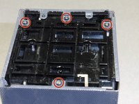
Turn the Jambox upside down. Peel the indicated rubber tabs off, using a plastic opening tool if necessary.
-
Remove the three T6, 7.0 mm screws under each rubber tab.
I used rubber cement to reattach the pads. That will hold them in place and be easily removable in future.
Can someone show a picture of the screws…and where they screw not…even just for form’s sake?
-
-
-
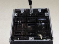
With the Jawbone logo facing towards you and with correct orientation, place the Jambox with the left end cap facing upward.
-
Unscrew indicated T6 9.7 mm screws.
-
Gently loosen the tabs from their anchor points so the bottom may be removed.
-
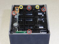
Flip the Jambox so the other end cap is facing up. The USB cable is on this side (metal grounding clip, indicated in orange). Repeat the above two steps.
Make sure you pay close attention when removing the screw marked with a red circle that is in the left most position, as there’s a small grounding plate that will be completely unrestrained and free to get nice and lost only to be found later leaving you not knowing what the hell it is or where it came from should you not secure it before removing the panel that that screw secures. That grounding plate is crucial for the safety of yourself and your speaker, because it bridges the USB-micro power input jack to the metal frame. That means that should you lose it and put the speaker back together without it, your speaker will not be able to ground out and should there occur any surge during your charge cycle, like during a freak lightning storm, or whatever, your speaker won’t able to discharge that surge, which will no doubt fry your speaker, and likely kill whomever poor bastard happens to grab the speaker, say to turn it off during said storm as a safety precaution. SAFETY FIRST!
Btw, the screw I mentioned is shown in the third picture, since that small detail might have some play over success or failure in finding it…lol. Whoops.
-
-
-
Pry up the bottom panel by lifting from the device.
-
Pull the bottom up. This may take a bit of force as the bottom is glued to device.
-
Once removed, the battery will now be visible.
No glue on mine. Only two clips on each side (that you can see clearly in step 3 picture).
Do not use force or you will break those clips.
@jemdem (I assume this is the “Jay” involved) after looking at the pictures 3.1, 3.2, 3.3, I still don’t see what I would normally expect a “clip” to look like. Maybe the corners act as clips? If not, I can’t ‘clearly’ determine them, but it’s a fairly busy looking area with lots of recesses and all, so maybe they’re just blending in well?
There’s a plug on each foot in one of the corners that isn’t meant to be removed. The left one and the right one (when viewed so the writing appears correct way up), both have three pins and one plug, with the pins occupying three of the four corners (northeast, northwest etc.) and the plug occupying the remaining fourth corner. The left foot has pins in the upper right, upper left and lower left, and the plug which is part of the foot and plugs into the frame, is in the lower right corner, while the right foot is opposite, having pins in upper left, upper right and lower right, and the plug in the lower right. If that was too many ‘left’s and ‘right’s to follow along with, then just remember that the plug is on the lower-inside corner on each. The screw is in the center of each foot. If you pull too hard, or attempt to guide your pick/spudger all the way around when separating the foot, you could slice it right off, though adhesive will be needed for reapplying so severing isn’t the end of the world.
This is a reply to the third comment, and sorry for the reply not being immediately following, or better still, not a reply, and instead just correcting my comment, but I can’t edit it…anyway, I noticed a mistake in my description. The plug on the right foot is in the lower LEFT corner, not the Lower right. My apologies to anyone who followed my instructions about that foot and ended up damaging it.
…continuing, the last foot needing removed is the upper center, when viewed so the writing on the feet is correct way up. And the plug on that foot is in the upper position, so only separate the bottom and both sides to access the screw in the center.
After continuing with the side pieces, the ‘clips’ that were holding the end pieces on were indeed at the corners and are NOT visible, clearly or otherwise. In fact only the ‘well’ or socket that each of the clips insert into are clearly shown, however the clips themselves are on the end caps, not the main body. If the speaker you are working on appears to have been dropped before and the corners are at all crumpled inward, take extra care to try and straighten them back to original shape before attempting to unclog the caps because not doing so could result in the clips breaking off. This may sound difficult, but I managed to straighten out all eight corners of the one I’m working on with no issues using a pair of needle nose pliers that are toothless so as to not introduce any bite patterns to the grill.
-
-
-
-
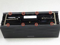
Unscrew the eight indicated T6 9.8 mm screws. Remove metal grounding plates.
-
-
-
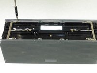
Once all eight screws are removed, pry the sides of the Jambox to lift the body from it's shell.
It was at this precise moment (removing the shell) that I felt a small part hit my knee as it fell from the assembly and land in the carpet. It appears to be a small stainless grounding tab (clip) that I THINK came from the mounting pole beside the Micro B port and may act as a support and ground for the body of the port. Seems to fit but I dunno.
It is a grounding clip and does belong on the power input jack and must be there if you want your speaker to safely ground out in case of a surge. Don’t lose it a please do put it back when reassembling your speaker. Also, it helps to read the comments attached to each step, if you had you would have read my comment regarding exactly this issue in previous steps. I’m glad you at least didn’t lose it when it fell, as it’s not something that is obvious when missing and most people wouldn’t even notice if it was lost.
-
-
-
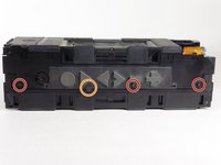
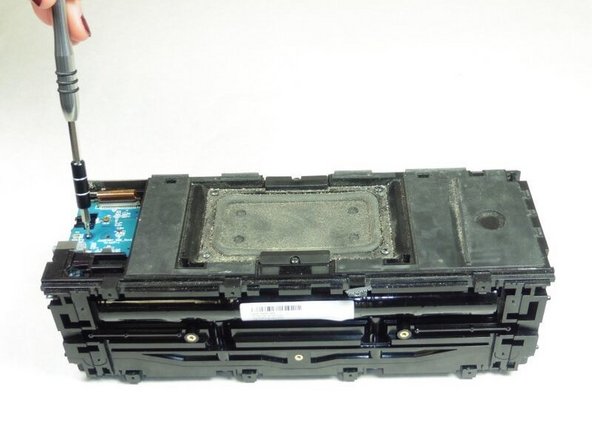
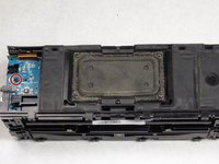
With the battery facing forward, remove the three indicated T6 9.5 mm screws.
-
Once the screws are removed, lift up the small plastic plate, revealing the auxiliary board underneath.
-
-
-
Turn the Jambox so that the button panel is visible.
-
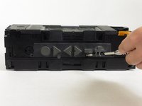
Remove the indicated screws, T6 9.6 mm.
-
-
-
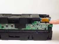
Remove the colored ribbon that connects the green button circuit board to the blue auxiliary board by using your finger to lift the small black tabs that clamp down the ribbon.
Thesmallblacktabsshouldnotbelifted.Theywillbebrokenbyliftingthem.Insteadyoushouldslidetheminthedirectionoftheribbon-paralleltotheboard.Theybreakeasilyandleaveyourdeviceworthlessifnotinstalledproperly.Nowmyspacekeynolongerworks.
This destroyed my fix. DO NOT TRY TO LIFT THE PLASTIC TABS!!! Despite what the instruction says it is impossible to do and will break with the slightest pressure upwards. I should’ve read the comment before from another user to slide the tabs OUT in the direction of the ribbon. I’ll keep going thru the steps to finish but this might prove worthless now.
IFIXIT needs to edit this!
-
-
-
Remove the indicated T6 7.4 mm screw holding the auxiliary board in place.
-
Carefully lift the auxiliary board up and off to the side.
-
-
-
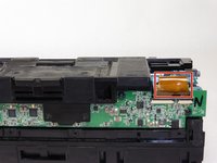
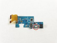
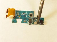
With the auxiliary board removed, use a soldering iron to heat the metal attaching the Micro USB port (indicated on the image).
-
Remove the Micro USB port.
-


To reassemble your device, follow these instructions in reverse order.
To reassemble your device, follow these instructions in reverse order.
crwdns2915084:0crwdne2915084:0

Cal Poly, Team 24-5, Lancaster Spring 2015 crwdns2935289:0Cal Poly, Team 24-5, Lancaster Spring 2015crwdne2935289:0
CPSU-LANCASTER-S15S24G5
crwdns2931471:04crwdne2931471:0
crwdns2935297:09crwdne2935297:0
crwdns2947412:07crwdne2947412:0
Hi, great guide. My jambox has a broken headphone input. Where can I buy one to solder in. Or can I buy an entire new aux board?
I'm also looking for a new headphone input. Where do I find one?
C Dare -
You guys keep failing to mention where to get replacement parts. Any ideas??
Where do I purchase the replacement auxiliary port?
Where do I purchase the replacement auxiliary port
Exactly the the part is missing..where do i get another?
So... does this mean I am supposed to solder the port back on? Is it attaching to the board? What is holding it on? The video shows using a paste, what is the best way to reattach it?
Can someone show the clips please in a photo?
kenneth keen - crwdns2934203:0crwdne2934203:0