crwdns2915892:0crwdne2915892:0
This guide will show you how to remove the charging port of a JBL Xtreme. This guide requires soldering skills.
crwdns2942213:0crwdne2942213:0
-
-
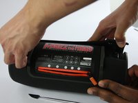
Locate the seams next to the 'feet' on the bottom side of the device.
-
-
-
Use the metal spudger to gently pry and lift the edge of the seam. The cover is held in place with plastic snaps that will make a popping noise when disengaged. !!Start with the back half, this will expose TWO Screws that need to be removed before lifting the front half.
Start with the back half, this will expose TWO Screws that need to be removed before lifting the front half.
Yes, the fact needs to be added that two screws need to also be removed to get the cover off. One side snaps off but the other is attached with two screws.
%#*@^@. I ripped the plastic things apart. Should have red the comments first. &&^&.
same here ;D just grabbed some glue and hope it will stick :D
Vorsichtig die Kante hochhebel, wo der Reissverschluss ist. Da ist die Hülle gesteckt. Die andere Seite hat Schrauben die man lösen sollte. Ansonsten zerstört man zu Beginn die Befestigung der einen Seite.
-
-
-
For the first part of the case: gently pull back the edges of the case rotating along the hinge opposite the opening seam illustrated in the second photo. Plastic snaps hold the cover in place.
-
For the second part of the case: there are 2 screws to be removed at the seam. Once removed, the case will come off completely without forcing.
Hello Where can I get a replacement cover?? Mine is damaged.
Did u ever find it they sell the covers?
Careful with this step, my JBL Xtreme case was also held in place by wo little srews !
It feels like you are “breaking” the cover, but in fact it seems to have a kind of “bending point” near the top of the cover by the exterior controls. Watch for the two screws to remove.
There is two screws holding the cover at its other end beside the plastic snaps
%#*@! broke one of the little snaps near the 2 screws. still holds tight though.. be careful when pulling them out. Also, don’t forget the screws
Die beiden Schrauben befinden sich jeweils neben den Füßen des Geräts. (Ein Foto von den beiden Schrauben wäre sehr hilfreich!)
-
-
-
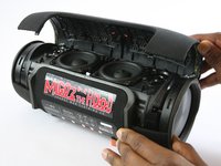
Unscrew the six 9.75mm Phillips head screws holding the bass radiator in place.
This was the most difficult part for me. The screws are pretty tight, I needed a larger screwdriver to get them out.
A PH1 or PZ1 Philips screw driver worked for me. For re- assembly it helps to place the speaker on the side with the other end facing down. That way you can exert more force. I would start with tightening all screws part way only and when they are all in place tighten them all the way (including the inner screw).
RTFM -
Achtung, die Bassstrahler sind mit dem Gehäuse über zwei “Klebedichtungen” verbunden. Diese müssen beim Zusammenbau wieder eingebaut werden.
Die Dichtung war bei mir nicht geklebt, sondern in die dafür vorgesehene Rille eingelegt. Sie ist mir beim Entfernen des Bassstrahlers zwar gerissen, ich konnte sie jedoch mit einem spitzen Kunststoffspachtel wieder in die Rille legen. Beim Zusammenbau muss man darauf achten, dass die Dichtung nicht herausrutscht. Am besten die Seite mit der Dichtung nach unten halten.
RTFM -
-
-
-
-
Once the screws have been removed, the bass radiator will easily lift free.
where can i buy these parts mate?
Where can I buy the bass radiators independently?
Ich empfehlen, erst den 7. Schritt auszuführen. So kann anhand der Kabel feststellen welcher Bassstrahler entfernt werden muss!
I would recommend to do the 7th step first. So can determine, based on the cable, which bass radiator must be removed!
Wo kann ich den die Ersatzteile kaufen bassstrahler und ein hochtöner???
Schritt sieben zuerst ist eine grandiose Idee, erspart einiges an Nerven.
die Linke Seite wie auf dem Bild ist die richtige. Dahinter findet man die Platine mit dem Anschlussstecker für den Akku. Somit sollte eigentlich 1ne Seite reichen.
So war es auch bei mir. Nur die linke Seite (von unten gesehen), also die Seite auf der der Zug vom „Reißverschluss“ endet, wenn er geöffnet ist, muss geöffnet werden. Dann kann man sich die Demontage der anderen Seite sparen!
RTFM -
attention, il y a entre chaque radiateur et le corps principal un joint très fin, tout autour. Il n'est pas collé et se détache facilement, l faut faire attention à le déplacer le moins possible, et à ne pas l'écraser, surtout si on retourne l'enceinte pour enlever l'autre radiateur (ce qui est inutile, il n'y en a qu'un à enlever pour accéder au connecteur de la batterie
-
-
-
Locate and disconnect the the three plugs indicated in these pictures.
-
-
crwdns2935267:0crwdne2935267:0Tweezers$4.99
-
Unplug the three ports from the previous step.
-
-
-
Locate the three Phillips head screws inside the zipper compartment and unscrew them.
-
Pull the zipper panel free from the device.
-
-
-
Under the zipper panel are eight more Phillips head screws. Unscrew them and carefully lift the battery cover.
-
-
-
Unscrew the three 11.88mm Phillips head screws highlighted in the picture.
-
-
-
Pull the Auxiliary board out.
hello, thanx for the great guide . i got a defekt xtreme and opened it like you write in your guide ,because my one doesn´t show any reaction when i plug power in. no charging or anything . as i opened it i saw that the capacitor on the last foto was burned out .
and than the big surprise , my auxilary board is not the same like yours . it´s 100 % a original xtreme and everything is simillar but on my bord is a 8 leg IC soldering -place. sorry for my bad english , it´s very difficult to explain . if anyone outthere can help me i send pictures from my board ,and you will be surprised that it has on the board a place for a IC ..
-
-
-
The first image highlights the charging port.
-
Locate 6 metal pins highlighted in the second image and use a solder iron to disconnect the pins.
Die Ladebuchse hat nur 3 Lötstellen…!
Ihr redete von der Ladebuchse aber Lötet die 3,5mm Klinke…
The final two pictures are incorrect. They show the pins for the Aux in, not the Coaxial Barrel charging jack. You can tell by the cord with the foam around it. In the first pic it's on the far side of the board in comparison to the charging jack, but when flipped, it's bear it. This is incorrect. You can also tell by the protruding tips of the jack when flipped, the larger one is the charging jack, but the flipped picture shows them soldering the pins pf the smaller jack. Please update, this may be causing many people difficulty.
If you want to hire me to write these articles instead in a precise and thorough manner, please reach out in a comment.
Regards,
David
-


To reassemble your device, follow these instructions in reverse order.
To reassemble your device, follow these instructions in reverse order.
crwdns2935221:0crwdne2935221:0
crwdns2935229:015crwdne2935229:0
crwdns2915084:0crwdne2915084:0

USF Tampa, Team 1-1, Sullivan Spring 2017 crwdns2935289:0USF Tampa, Team 1-1, Sullivan Spring 2017crwdne2935289:0
USFT-SULLIVAN-S17S1G1
crwdns2931471:04crwdne2931471:0
crwdns2935297:028crwdne2935297:0
crwdns2947412:02crwdne2947412:0
Please I have a JBL XTREME that sparks each time I plug it. What could be the cause
Hi. Can someone advise where a replacement charging port can be sourced? I.e., so I can desolder the existing one and solder a new one in its place. The existing one is badly corroded so the unit won't charge. Thanks Andy