JBL Flip 3 USB Port Replacement
crwdns2944107:0crwdnd2944107:0College Studentcrwdnd2944107:0crwdnd2944107:0crwdnd2944107:06crwdnd2944107:0crwdne2944107:0
crwdns2944111:0Sun 28, 2025crwdne2944111:0
crwdns2942213:0crwdne2942213:0
crwdns2943215:0crwdne2943215:0


crwdns2944105:0crwdne2944105:0
-
-
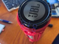
Remove the speaker grill using hands or a standard spudger.
-
Re-assembly Notes
-
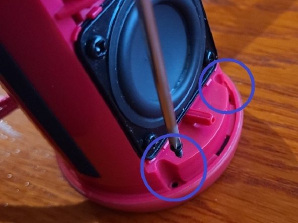
Note the three alignment pins on the inner part of the housing and take care to line these up and insert the pins into the receivers on the chassis fully
-
With the pins fully engaged in the middle, pull the long edges away from the chassis slightly and then squeeze to engage the plastic clips into the chassis (two per edge, at the top and bottom.
-
-
-
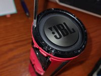
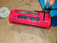
Remove the ten screws of the outer frame.
-
Six (6) screws along the thin long edge that are screwed in the chassis
-
Four (4) screws ( 2 per end) holding the ends to the chassis.
-
Reassembly Notes
-
Do not over-tighten screws.
ACHTUNG: Dazu muss man zum einen auf der Lautsprecherseite an beiden Enden jeweils 2 Schrauben lösen (siehe “Step 3”, warum auch immer einem das erst in einem Folgeschritt gezeigt wird), zum anderen auf der anderen Seite (neben den Bedienelementen) jeweils 3 Schrauben auf beiden Seiten. Versäumt man letzteres (wie es mir ergangen ist, weil in der Anleitung ja nichts davon stand), geht der äußere Rahmen auch ab, allerdings brachen dann die dünnen Plastikösen, in denen die 6 Schrauben steckten, ab! Was für den späteren Zusammenbau und die Stabilität des Gehäuses alles andere als günstig wäre (und bei mir so ist ;-(
/!\ WARNING /!\
Remove the screws of step 3 (each side) + 3 screws on each side. There’s a total of 10 screws to remove before removing the piece as shown.
Also pay attention to the plug hatch.
(hope you’ll read this before damaging your speaker)
-
-
-
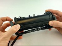
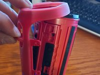
Pull on one end gently and remove the outer frame.
-
Remove the silicone button cover
-
Re-assembly Notes
-
Insert the silicone button cover first.
-
Line-up the bottom end first and carefully guide the USB port cover through the matching hole as you insert the top end.
To avoid confusion and possible damage I feel that this should be step 2 instead of step 3, or should be added to step 2. A mention of how many screws need loosening would help tons too.
My unit required the loosening of 4 total #00 Phillips screws exposed on both sides and also required the removal of 6 additional #00 Phillip's screws holding down the outer frame on either side of the long section.
-
-
-
Remove the twelve screws that hold the two speaker end caps (6 per end)
-
Re-assembly notes
-
Align the two holes that are closest together (and pin underneath) to match the chassis holes first to align the entire end cap.
-
Tighten the six (6) screws per end cap (12 total). Do not over-tighten.
Not sure if my unit is a later revision or had been opened up before, but the screws I encountered holding the drivers in place were 8 #2 Phillip's screws of similar measurement.
-
-
-
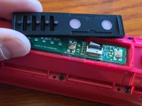
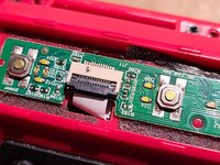
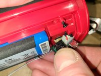
Carefully lift the retaining tab and pull ribbon cable out of the connector.
-
Note: Black plastic tab can fall out easily, so note orientation in the picture before re-inserting tab if it fell out.
-
For re-assembly, guide ribbon cable through the hole before re-inserting and closing the tab.
-
-
-
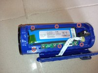
Remove the six (6) screws retaining the control panel to access the USB Port (battery is also visible).
-
For re-assembly: do not overtighten screws.
-
-
-
From the end cap side, remove the silicone holding the wires in place.
-
Proceed carefully Make sure the speaker is powered off. Avoid cutting the wires. A plastic ustensil is probably best, or a very small, dull screwdriver.
-
This took me about 30 minutes and I forgot to take pictures.
-
Disconnect the AUX input plug and then pull that wire out from under the PCB so it can be aligned with the hole.
-
Re-assembly Notes.
-
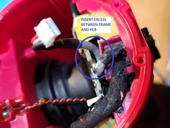
Push the AUX wiring between the PCB and the chassis.
-
Plug the AUX connector back in.
I removed all the six screws but the cover doesn't budge. Could it be glued?
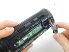
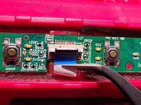
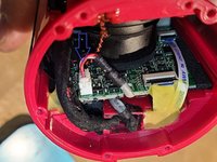
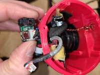
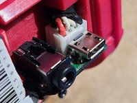
After removing the screws, you can lift up the upper part containing the switches, the LEDs and the cover of the USB port, hence revealing the view on the battery and the delicate ribbon cable as shown above.
However, the USB plug and its daughterboard are still attached to the motherboard. In order to replace the USB plug, we would need further instructions on how to remove ist. I do not understand why the guide ends at this point. Without this information, the guide seems pretty useless to me.
Additionally, In my case, the USB plug, its daughterboard and the ribbon cables are fixed to the main compartment with some sort of black as well as yellow glue. Any idea how to remove that, without further damage?
Bei mir ist das Flachband gerissen, als ich den Akku wechseln wollte. Kann man das noch reparieren? Bzw gibt es eine möglichkeit es auszutauschen?
-
-
-
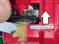
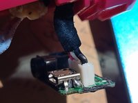
Pull up on the USB Port PCB to break the lower glue/seal
-
Pull PCB out and rotate upward to align wiring
-
Gently guide wires at the end cap through the hole to extend the USB Port PCB as far out as possible.
-
Re-assembly Notes Pull the wiring from the end cap while aligning and inserting the PCB back in.
-
-
-
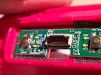
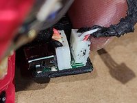
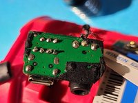
WARNING! The two white connectors are not plugs. Do not attempt to pull them out.
-
IMPORTANT Take note or a picture of the wiring color and orientation for re-assembly later.
-
Unsolder the two connectors from the PCB.
-
-
-
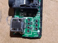
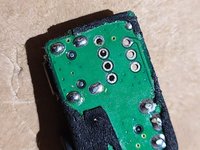
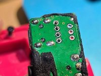
Unsolder the old USB Port.
-
WARNING! There are two different JBL Flip 3 speaker USB Ports. Order a replacement port of the same type that you have in your speaker.
-
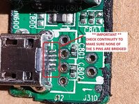
Solder the new USB Port (5 pins and 4 mounting tabs)
-
Perform a continuity check to make sure none of the pins are bridged.
-
-
-
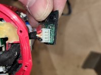
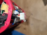
Align the connector holes in the correct orientation for each plug, and solder to the USB Port PCB.
-
-
-
Gently return the USB Port PCB to it's location while gently pulling on the wires at the end.
-
Reconnect temporarily the AUX connector
-
Reconnect temporarily the Ribbon Cable to the control panel
-
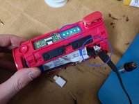
Power on the speaker, and then insert a USB charger to ensure that the battery charges properly.
-
Test the AUX input to ensure it is still working.
-
Following a successful test, disconnect the control panel ribbon cable and the AUX plug.
-
Re-assemble the speaker in reverse order, taking note of the re-assembly notes provided at each step.
-


To reassemble your device, follow these instructions in reverse order.
To reassemble your device, follow these instructions in reverse order.
crwdns2935221:0crwdne2935221:0
crwdns2935229:051crwdne2935229:0
crwdns2947821:0crwdne2947821:0
crwdns2947823:0crwdne2947823:0


crwdns2915084:0crwdne2915084:0

USF Tampa, Team S1-G2, Leahy Spring 2017 crwdns2935289:0USF Tampa, Team S1-G2, Leahy Spring 2017crwdne2935289:0
USFT-LEAHY-S17S1G2
crwdns2931471:05crwdne2931471:0
crwdns2935297:018crwdne2935297:0
crwdns2947412:024crwdne2947412:0
how can i find the part..email me at leedeen2000@yahoo.com plz
I feel that the difficulty is just because of the lack of detail on the instructions. I also need to find the part, but where do I get it? I searched on eBay, Amazon and got nothing. That means that I have to scavenge this part from another one?
i already got step 5, but i need know how i can get the replacement ? Any idea ?
Looking for the part 2…
Looking for the same thing…
Where can I purchase the replacement charger port from?
tony@tlm-laser.com
BR Tony Dain
Where can I purchase the charger port from?
tony@tlm-laser.com
BR Ant
Same, where is this board available? Would this work to fix the USB charger?
Strip the broken part off the board and solder the wires to the breakout.
Same problem here and where to get the replacement part?
where do i get the replacement part email me : ezequiel1488@outlook.com
There could have been a lot more detail put into this. From what I can tell, the charging port itself has to be desoldered and replaced. I recommend AliExpress to buy the part.
Where can we get that part, the PCB chip.
Email me please.
david8o8l13@gmail.com
USB board assembly part not available. Sorry Charlie !
Where can we get the usb pcb board set for replacement?
Where can we get or buy the usb pcb board for replacement?
These instructions are missing crucial information and steps are presented out of order to how disassembly should be done.
I fully agree. I was very content with all the repair guides I found on ifixit so far, but this guide is really poor. Missing steps, wrong order, and it does not even lead to the solution that it pretends to deliver. I am sorry, if the authors are not willing to improve and to complete this guide, it should better be removed, in order to be replaced by something more useful.
where are the parts
Where can we get or buy the usb pcb board for replacement? Same questions already post it but answer.
The USB socket I used was from ebay. Just search for 'micro USB 4 vertical legs' and you'll see the parts.
https://www.ebay.com/sch/i.html?_from=R4...
Easily found.
Mi puerto está en corto circuito como lo debo reparar
As mentioned in many of the comments, this guide was incomplete, so I did a re-write based on my own experience. If it is not yet approved, you can view by selecting the "unverified guide" link above.
@michelk17 Thank you, that's how it should be done. The guides at iFixit are wikis and can -should- be improved by everyone.
VauWeh -
I found my replacement USB Port here on ebay. Very friendly and they made sure that I got the correct one.