crwdns2915892:0crwdne2915892:0
Having trouble with your scroll wheel trying to go in the opposite direction when scrolling?
Use this guide to replace the scroll wheels rotary encoder/mouse roller wheel encoder.
Dissasembling the device will probably void warranty.
crwdns2942213:0crwdne2942213:0
-
-
Soldering iron and soldering skills will be required.
-
Before starting with the repair, please note that you will require a rotary encoder for scroll wheel size 13mm.
-
Recommend purchasing a new set of mouse feet/skates.
-
-
-
Since almost all components inside the mouse are screwed down to the bottom of the mouse, we will need to remove the top part.
-
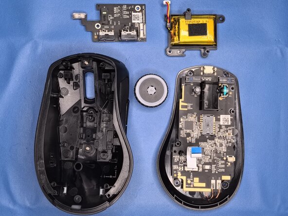
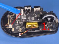
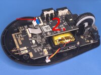
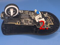
1st. Let's put the mouse into an OFF position. [IMAGE 1]
-
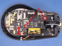
2nd. Let's remove mouse feet. There are three of them on the bottom part of the mouse as seen in the picture. If you haven't purchased replacement feet, I recommend that you peel the mouse feet to the side only where the screws are located so you don't lose adhesion so they don't fall off during use or use glue to reapply mouse feet. [IMAGE 1]
-
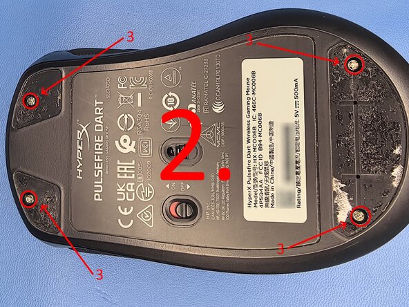
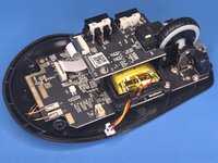
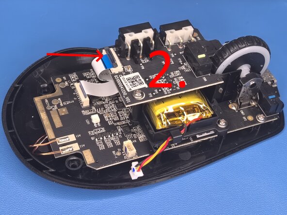
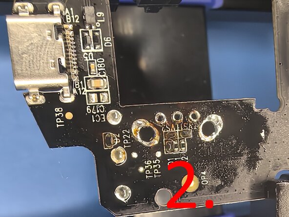
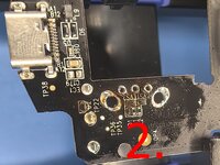
3rd. We have to remove 4 screws as can be seen in the picture. Three screws are Philips 3 and one screw is Torx 6. [IMAGE 2]
-
After that, the top part of the mouse should pop right off with a little bit of force.
-
-
-
Let's disconnect the battery by pulling on the connector as can be seen in the picture (the connector that we need to disconnect is more white then the part that's soldered to the PCB).
-
If the connector is not sliding out easily, move it from left to right and pull at the same time and it should pop right out.
-
-
-
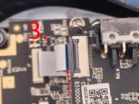
1st. We have to lift the black lever. You can use a pry tool as can be seen in IMAGE 1
-
2nd. Once the lever is lifted you can pull the cable out of the connector. [IMAGE 2]
-
When reassembling the device make sure you insert the cable all the way. [IMAGE 3]
-
-
-
-
First, let's remove two Philips 1 screws as can be seen in the IMAGE 1.
-
Then you will have to lift the PCB for a few milimiters, and then you have to rotate the PCB for approximately 45° to slide the board out of the scroll wheel as shown in IMAGE 2.
-
-
-
Since the battery is already disconnected, we just have to remove the two Philips 1 screws.
-
Lift the battery with the battery cage straight up.
-
-
-
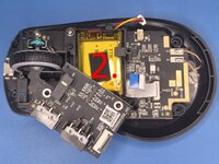
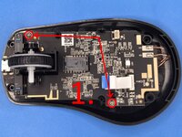
To remove the scroll wheel, we have to first unscrew the main PCB.
-
The main PCB is held down by two Philips 1 screws. [IMAGE 1]
-
Once you have removed the two screws, lift the pcb in the front part where the charging port is located. [IMAGE 1]
-
Lift the pcb for at leats 3cm then pull the scroll wheel to the left and then straight up. [IMAGE 2]
-
Try not to damage the two wires that are at the back of the PCB connected to the wireless charging pad. For the repair that we are doing, removal of it is not required.
-
-
-
Now we have to desolder the scroll wheel rotary encoder (Mouse roller wheel Encoder).
-
Put your pcb into pcb holder or use helping hands. If you don't have any of these, use something to lift it away from plastic or any material that can be melted or ignited.
-
You can use a soldering iron or heat gun to desolder the rotary encoder. My preferred method is using soldering iron, so that's what i did.
-
The rotary encoder is held in with 5 pins. You have to desolder all 5 pins, apply flux around all 5 pins and use desoldering braid with soldering iron to remove solder from pins. [IMAGE 1]
-
If you have problem with melting solder, add new fresh solder to make it easier to melt. If your soldering skills are not great, you can use pliers to cut off pins of the rotary encoder and remove each pin by itself. Make sure that you have removed solder from all holes otherwise the new rotary encoder will not fit in. [IMAGE 2]
-
My preferred soldering iron temperature is 360°C, but you can use whatever temperature works for you. If you are using a flux that has to be cleaned off, I recommend that you use isopropanol. Since I'm using no clean flux, I don't have to do that.
-
-
-
Rotary encoders side pins are bent, so you will have to apply some pressure for them to snap into place. Please do not try to straighten the pins, they are bent for a reason!
-
Make sure that you position your new rotary encoder straight so you don't run into any problems later.
-
When adding solder to the pins, please apply enough solder to cover the whole hole. Add flux for solder to stick only to designated spots.
-
-
-
Once you have finished STEP 9, to reassemble the device, follow instructions in reverse order from STEP 7.
-
Make sure that you don't forget to put the plastic for power switch back in the bottom portion of the device and that the wireless charging cables don't make contact with each other.
-


Congratulations!
crwdns2947412:05crwdne2947412:0
Hello i have a question. I have the same mouse and the axis on my scroll wheel broke and I bought a new one but it's not the same as the previous one. Now I'm wondering if I can cut off the part where the LED lights for the scroll wheel are? Thank you!
Hi. Sorry for the late response mate. If I understand right, you want to cut away the top pcb the portion where the LED is soldered on? Can you provide a picture where you want to cut off?
Nemeš -
This part I need to cut. Thank you for answering!
From the look of it, you should be fine with cutting it off, but you would have to be careful not to make a short circuit between the traces when you cut it off. But I would not recommend cutting it off. It's night here. Tomorrow afternoon I can open up my mouse and check if it's actually safe to do so if you want.
Nemeš -
Thank you! I really appreciate your help!