crwdns2915892:0crwdne2915892:0
Use this guide to service the Makita Jack Hammer HM1203C 2010. This includes replacing seals, grease, and motor brushes.
Wherever there’s grease, make sure to clean it off and replace it with new grease. The recommended grease is Makita 181490-7.
Throughout this guide, the service kit parts will be referred to by their part description in the service kit, i.e. “O-ring 23”.
crwdns2942213:0crwdne2942213:0
-
-
Use a Phillips #2 screwdriver to remove the three screws securing the motor cover.
-
-
-
Pull the brush connector straight off of its spade to disconnect the brush.
-
-
-
Use a pick or small flathead screwdriver to pull the brush retaining spring off of the brush.
-
-
-
Lift the brush out of its motor housing while holding the retaining spring out of the way.
-
Repeat the last three steps to remove the second brush.
-
-
-
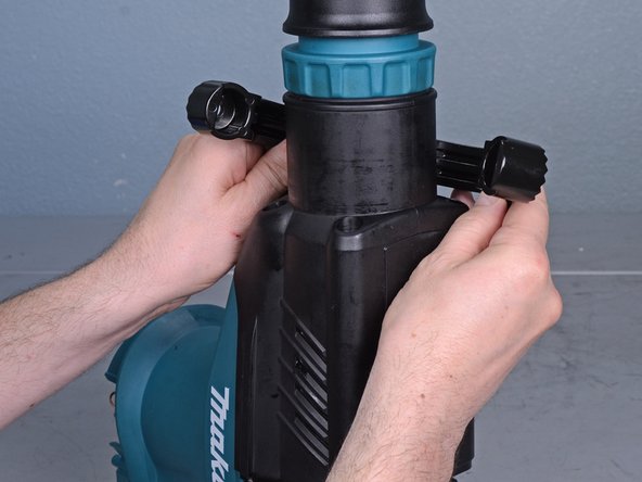
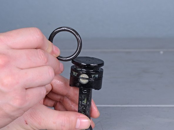
Unscrew the knob securing the side handle.
-
-
-
Remove the bolt securing the side handle.
-
Remove the side handle.
-
-
-
Use a Phillips #2 screwdriver to remove the six screws securing the handle assembly.
-
-
-
Pull the handle assembly away from the hammer, but do not completely remove it yet. It's still connected to the hammer by a power cable.
-
-
-
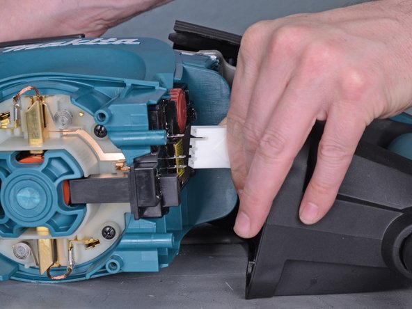
Pull the power connector straight off of its plug.
-
Remove the handle assembly.
-
-
-
Use a small pry bar or flathead screwdriver to pry the rubber front cap off of the hammer.
-
-
-
Use a pair of snap ring pliers to expand the snap ring on the front of the hammer.
-
Remove the snap ring.
-
-
-
Remove the washer on the front of the hammer.
-
-
-
Lift the front cover off of the front of the hammer.
-
-
-
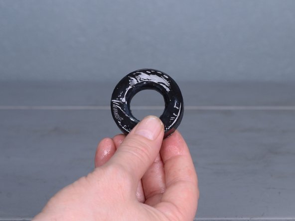
Lift the rubber ring off of the front of the hammer.
-
-
-
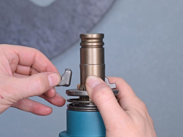
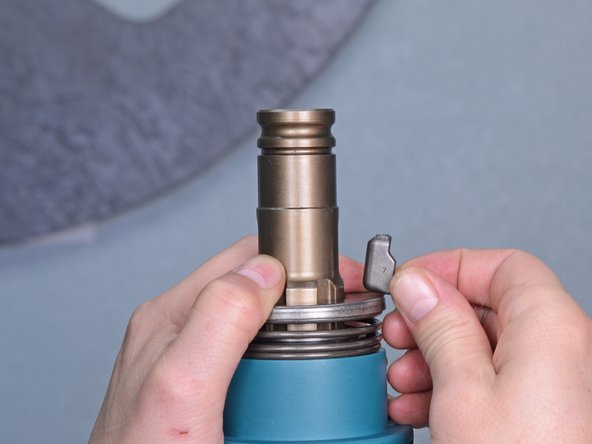
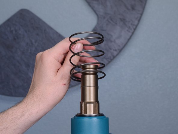
Compress the spring and hold it down while you pull the two retainers out of their slots and remove them.
-
-
-
-
Remove the spring guide.
-
Remove the spring.
-
-
-
Remove the front barrel cover.
-
-
-
Remove the 4 mm hex bolt securing the barrel cover.
-
-
-
Lift the barrel cover straight up and remove it.
-
-
-
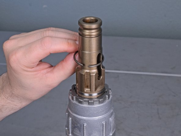
Use a pair of snap ring pliers to expand the snap ring securing the bolt holder.
-
Remove the snap ring.
-
-
-
Lift the washer off of the bolt holder and remove it.
-
-
-
Remove four 6 mm hex bolts securing the barrel.
-
-
-
Lift the barrel straight up and remove it.
-
-
-
Use an angled pick to pull the washer and rubber ring 39 out of the barrel.
-
-
-
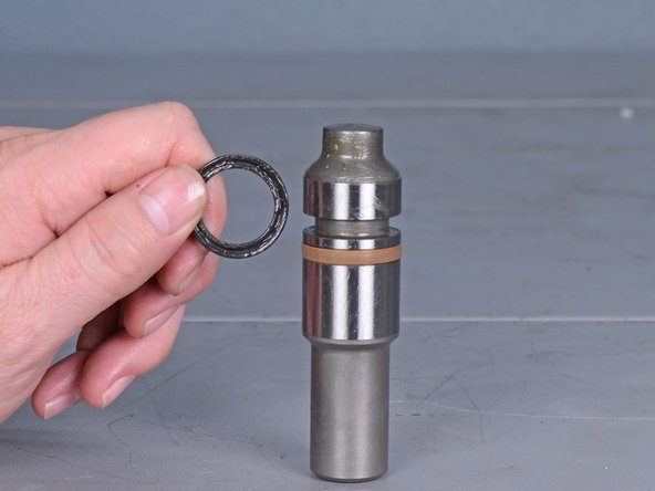
Lift the upper-most rubber ring straight up and remove it from the bolt holder.
-
-
-
Lift the upper-most washer straight up and off of the bolt holder.
-
-
-
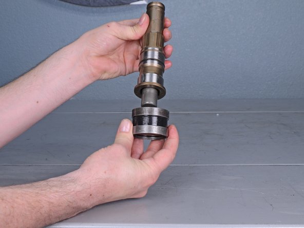
Grasp the bolt holder, rubber ring 24, and the two metal sleeves below it, and lift it off of the cylinder.
-
-
-
Separate the rubber ring 24 and the two metal sleeves from the bolt holder.
-
-
-
Separate the rubber ring 24 from the two metal sleeves.
-
Remove the rubber ring 24.
-
-
-
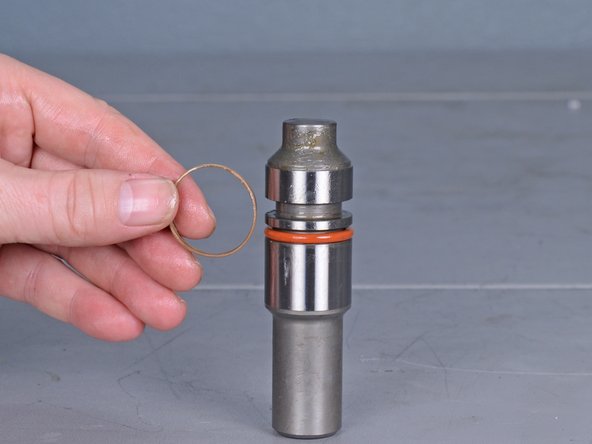
Use an angled pick to lift the O-ring 35.5 out of its groove on the bolt holder.
-
Remove the O-ring 35.5.
-
-
-
Use a long punch, long flathead screwdriver, or a thin, long bar to push the bolt out of the bolt holder.
-
Remove the bolt.
-
-
-
Use an angled pick to pry the X-ring 21 out of its groove in the bolt.
-
Remove the X-ring 21.
-
-
-
Use an angled pick to pry the fluoride ring 28 out of its groove in the bolt.
-
Remove the fluoride ring 28.
-
-
-
Use an angled pick to pry the O-ring 23 out of its groove in the bolt.
-
Remove the O-ring 23.
-
-
-
Lift the cylinder straight out of the aluminum housing.
-
-
-
Pull the striker out of the cylinder.
-
-
-
Use a pick to pry the striker O-ring 31.5 out of its groove on the striker.
-
Remove the striker O-ring 31.5.
-
-
-
Use a 5 mm hex key to remove the six screws securing the aluminum housing.
-
-
-
Separate the aluminum housing from the rest of the hammer.
-
-
-
Slide the fix guides and the rubber plate out of their slots on the housing and remove them.
-
-
-
Use a Phillips #2 screwdriver to remove the four screws securing the piston cover.
-
-
-
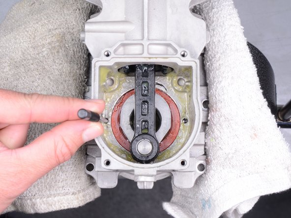
Rotate the crank shaft and the connecting rod so that the rod is vertical and the end is at the very bottom of the housing.
-
-
-
Use an arbor press and a custom punch to carefully press the crank shaft, bearing, and gear assembly out of the housing.
-
If you don't have access to a press or custom tool, use a punch and a hammer to tap the crank shaft until the whole crank shaft, bearing, and gear assembly starts to slide out.
-
-
-
Pull the connecting rod and the piston out of the housing.
-
-
-
Use a pick to pry the piston O-ring 31.5 out of its groove in the piston.
-
Remove the piston O-ring 31.5.
-
-
-
Use a pick to pry the O-ring 35 out of its groove in the piston.
-
Remove the O-ring 35.
-


To reassemble your device, follow these instructions in reverse order.
To reassemble your device, follow these instructions in reverse order.
crwdns2935221:0crwdne2935221:0
crwdns2935229:08crwdne2935229:0

crwdns2947410:01crwdne2947410:0
I have been having a hard time with the furthermost forward snap rings. Removing and reinstalling. Is your set of snap ring pliers modified in any way? Drew, HD tech store 6381.