crwdns2915892:0crwdne2915892:0
Use this guide to replace the motherboard in your HTC Vive Pro 2 headset.
Some photos in this guide are from a different model and may contain slight visual discrepancies, but they won't affect the procedure.
Power off and unplug your headset before you begin your repair.
crwdns2942213:0crwdne2942213:0
-
-
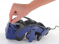
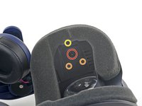
Rotate the head strap forward as far as it will go.
-
-
-
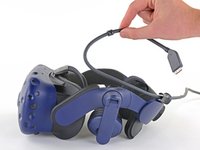
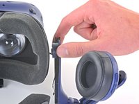
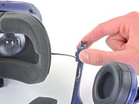
Unplug the All-In-One Cable from your headset.
-
-
-
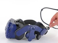
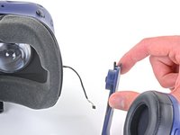
Remove the All-In-One Cable from the cable guides along the left side of the head strap.
-
-
-
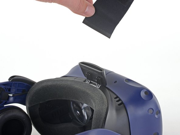
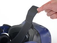
Separate the top strap from itself where the Velcro secures it.
-
-
-
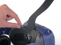
Peel back the Velcro securing the rear of the top strap.
-
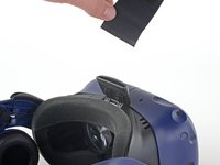
Feed the top strap out through the head strap to partially remove it.
-
-
-
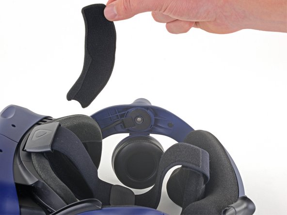
Feed the top strap through the clip near the front of headset to fully remove it.
-
-
-
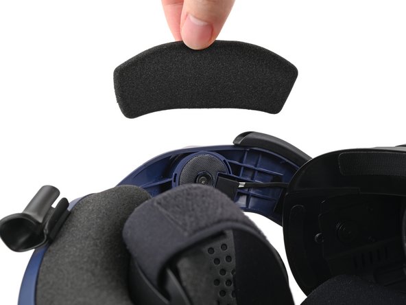
Peel off both front side foam pads to uncover the speaker wires.
-
-
-
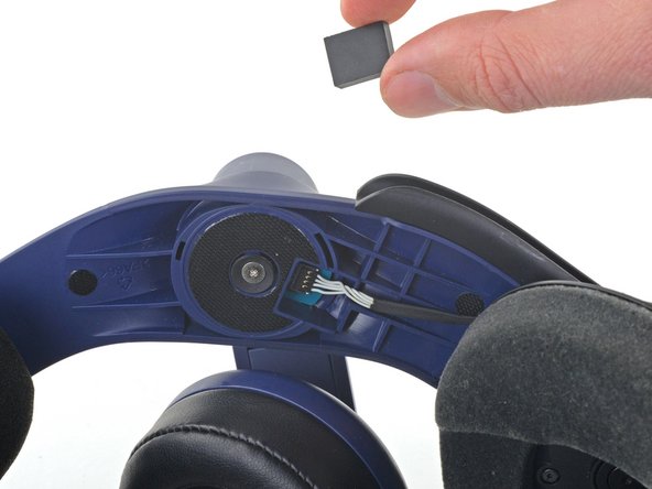
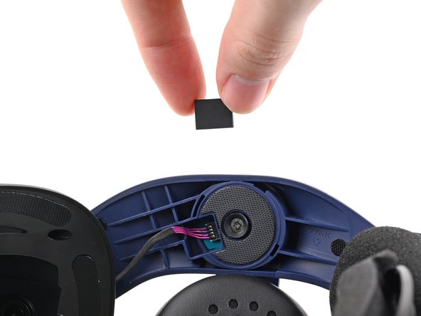
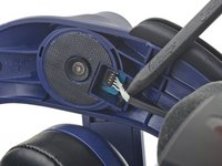
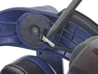
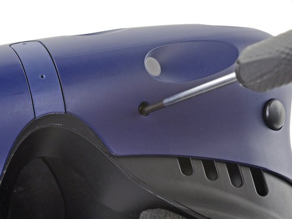
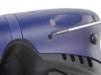
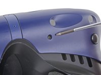
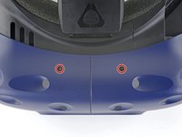
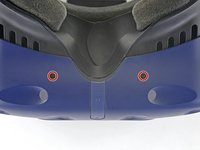
Use the point of your spudger to pry out the two rubber spacers next to the headphone screws.
-
-
-
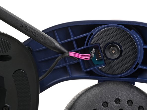
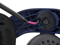
Use the point of your spudger to pry up and disconnect both the left and right headphone speaker wires.
-
-
-
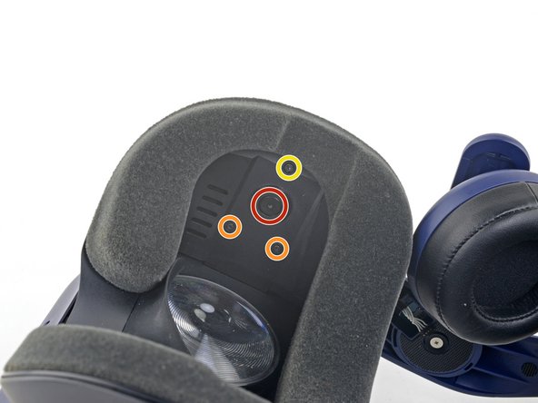
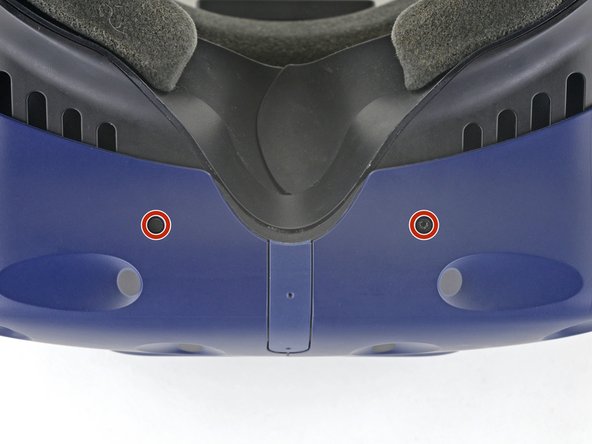
Use a T6 Torx screwdriver to remove the two 12.1 mm screws (one on each side) securing the head strap to the headset.
-
Use a T5 Torx screwdriver to remove the following screws securing the head strap to the headset:
-
Four 3.9 mm screws (two on each side)
-
Two 4.1 mm screws (one on each side)
-
-
-
Remove the two plastic spacers underneath the previously removed Torx T6 screw.
-
-
-
Thread the headphone speaker wires out through both ends of the head strap.
-
-
-
-
Use a T6 Torx screwdriver to remove the four 3.9 mm screws (two on top, two on bottom) securing the outer shell to the headset.
-
-
-
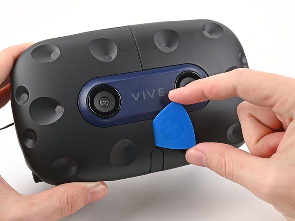
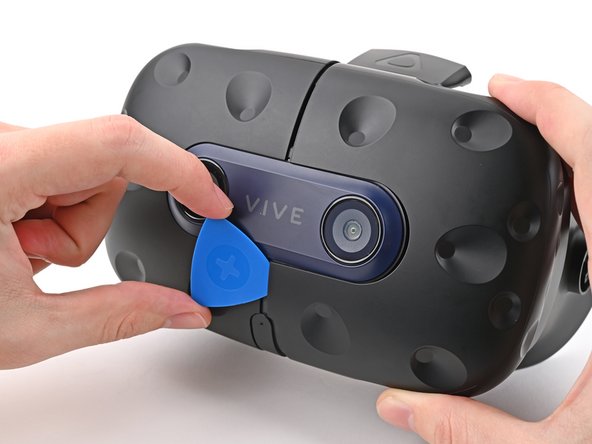
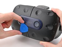
Insert an opening pick into the seam between the two halves of the outer shell.
-
Slide the opening pick through the seam to dislodge the clips securing it to the headset.
-
-
-
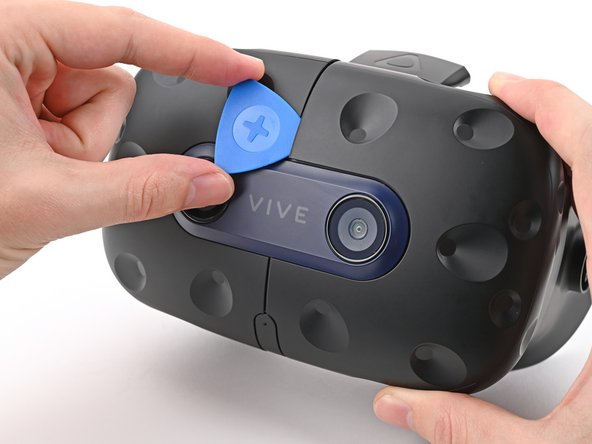
Continue sliding the opening pick through each seam until all clips have been dislodged.
-
-
-
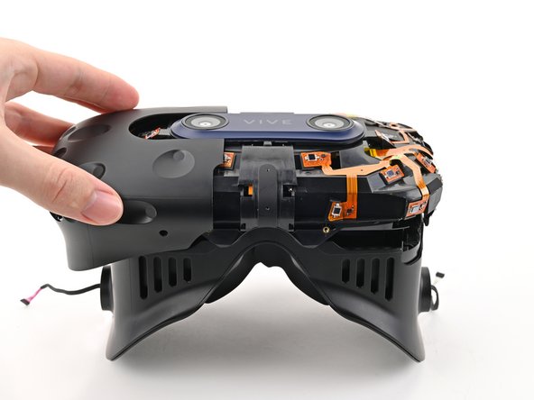
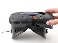
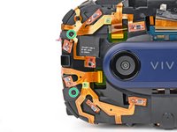
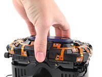
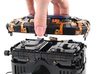
Carefully slide each half of the outer shell off of the sensor array.
-
-
-
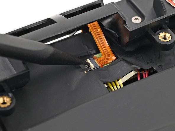
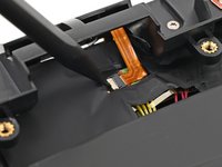
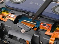
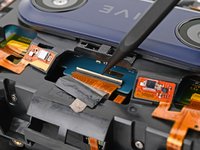
Use the point of your spudger, or a clean fingernail, to flip up the locking tab on the microphone ZIF connector on the daughterboard.
-
-
-
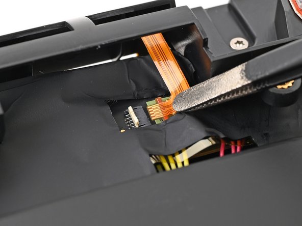
Use tweezers, or your fingers, to pull the microphone cable straight out of its socket.
-
-
-
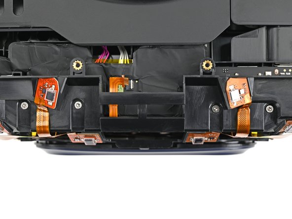
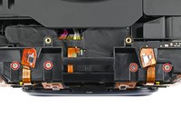
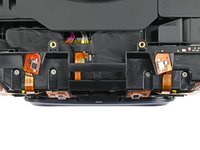
Use tweezers, or your fingers, to peel the conductive fabric off the sensor array ZIF connector on the motherboard.
-
-
-
Use your spudger, or a clean fingernail, to flip up the locking tab on the sensor array ZIF connector.
-
-
-
Use your fingers to grip the left and right sides of the sensor array cable and pull it straight out of its socket.
-
-
-
Use a T5 Torx screwdriver to remove the four 3.0 mm‑long screws securing the top of the sensor array.
-
-
-
Use a T6 Torx screwdriver to remove the four 3.8 mm‑long screws securing the front of the sensor array.
-
-
-
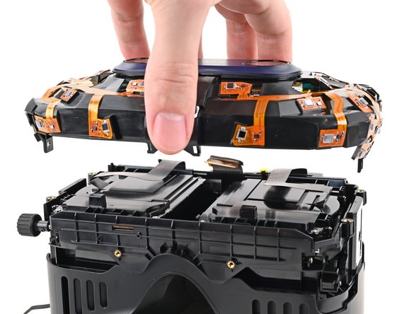
Lift the sensor array straight off the lens assembly and remove it, making sure you thread the cable through its slot.
-
-
crwdns2935267:0crwdne2935267:0Tweezers$4.99
-
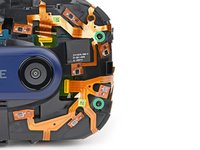
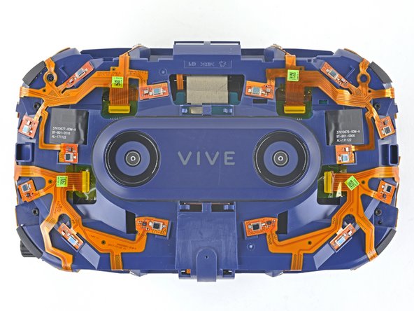
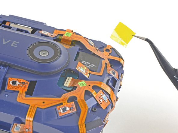
Use a pair of tweezers or your fingers to remove the four pieces of Kapton tape covering the ZIF connectors.
-
-
-
Use the flat end of your spudger to flip up the locking flap on a ZIF connector on the sensor array.
-
Use the pointed end of your spudger to disconnect the ribbon cable from its ZIF connector.
-
Repeat this procedure for all four of the ZIF connectors.
-
-
-
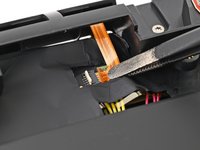
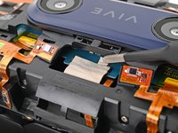
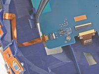
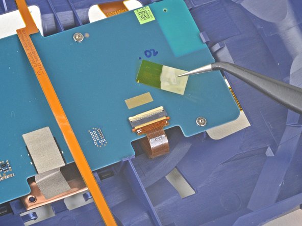
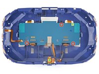
Use a pair of tweezers to remove the Kapton tape covering the two ZIF connectors on the back of the motherboard.
-
-
-
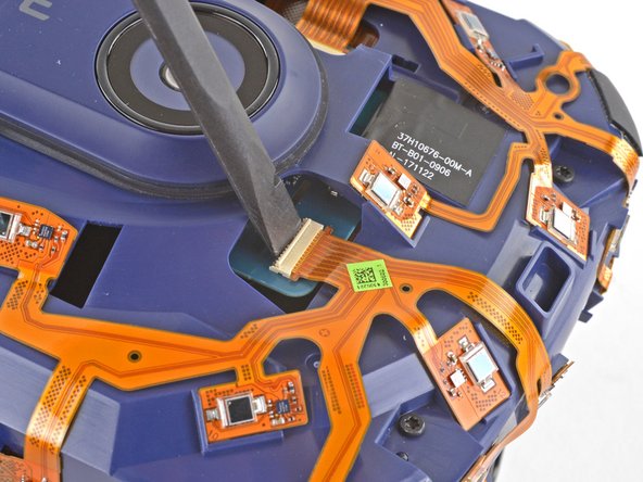
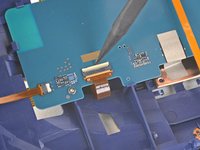
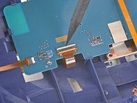
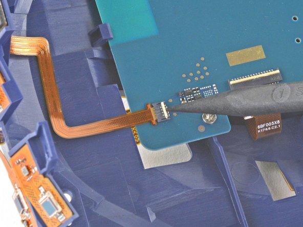
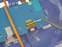
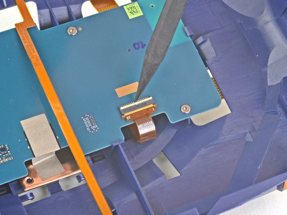
Use the point of your spudger to unlock the ZIF connector on the back of the motherboard.
-
Use the spudger, or your fingers, to slide the ribbon cable out of its socket.
-
-
-
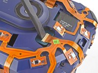
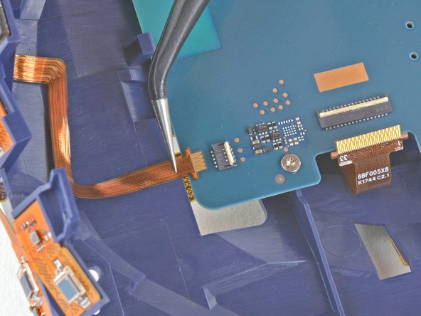
Use the point of your spudger to unlock the ZIF connector on the back of the motherboard.
-
Use the spudger, or your fingers, to slide the ribbon cable out of its socket.
-
-
-
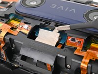
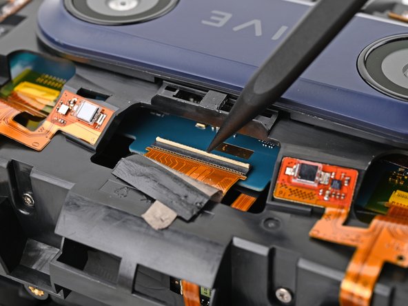
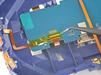
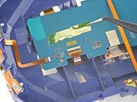
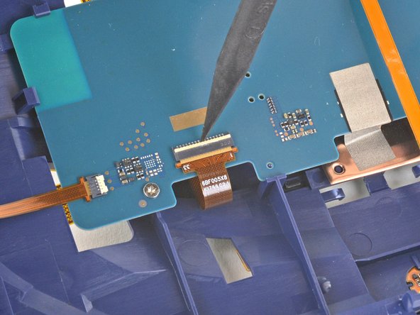
Use a pair of tweezers to remove the Kapton tape covering the remaining ZIF connector on the back of the motherboard.
-
-
-
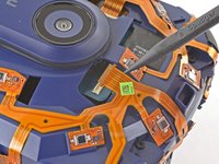
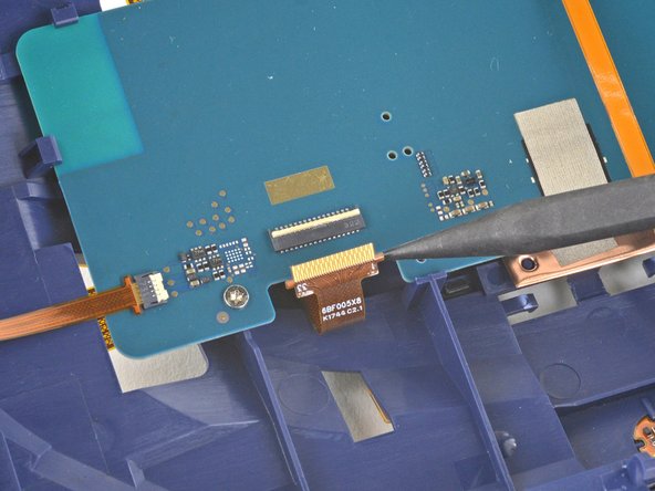
Use the pointed end of your spudger to unlock the ZIF connector on the back of the motherboard.
-
Use the spudger, or your fingers, to slide the ribbon cable out of its socket.
-
-
-
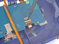
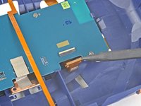
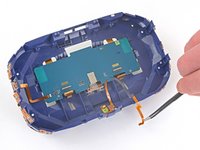
Reposition the long ribbon cable covering the back of the motherboard so it's out of the way.
-
-
-
Use a T5 Torx screwdriver to remove the three 3.0 mm‑long screws securing the motherboard to the sensor array.
-
-
-
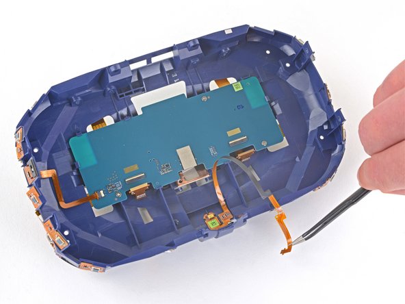
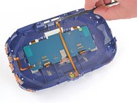
Apply a heated iOpener to the back of the motherboard for one minute to soften the light adhesive securing it to the sensor array.
-
-
-
Remove the motherboard from the sensor array.
-


Compare your new replacement part to the original part—you may need to transfer remaining components or remove adhesive backings from the new part before installing.
To reassemble your device, follow the above steps in reverse order.
Take your e-waste to an R2 or e-Stewards certified recycler.
Repair didn’t go as planned? Try some basic troubleshooting, or ask our Answers community for help.

