crwdns2915892:0crwdne2915892:0
Use this guide to replace a worn-out battery.
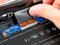
crwdns2942213:0crwdne2942213:0
-
-
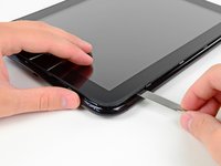
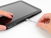
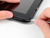
In the following steps, you will use a metal spudger to lift the front panel out from the rear case of your TouchPad.
-
-
-
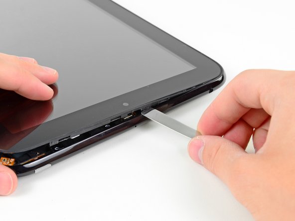
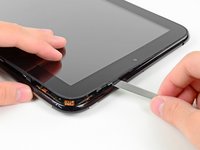
Insert a flat metal spudger in the gap between the rubber outer ring on the front panel assembly and the black plastic rear case near the USB connector.
-
Pry the front panel assembly up from the rear case, being careful not to damage the LCD or the glass panel.
-
-
-
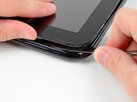
As in the previous step, use a spudger to pry the front panel up from the rear case along its long edge on the volume button side of the TouchPad.
-
Continue to pry the front panel assembly up along the volume button side of the TouchPad until there is a gap between it and the rear case.
-
-
-
Pry up the front panel assembly along the top edge of the TouchPad.
-
-
-
Pry up the front panel along the edge closest to the home screen button.
-
-
-
Before lifting the free side of the front panel up from the rear case, you may need to release it from the plastic retaining clips holding it down.
-
Use your metal spudger to pull the stuck retaining clips away from the edge of the front panel.
-
-
-
After freeing the retaining clips, lift the front panel assembly away from the rear case.
-
-
-
Use the attached black tab to pull the display data cable straight up and out of its socket on the motherboard.
The ribbon can be adhered to other parts placed under it. You'll have to separate them tighly so you don't damage the ribbon.
-
-
-
Use your fingernail to carefully flip up the retaining flaps on the two digitizer ribbon cable ZIF sockets.
-
Pull the digitizer ribbon cable straight out of its two sockets on the motherboard.
-
-
-
Remove the front panel assembly from the rear case assembly.
-
-
-
-
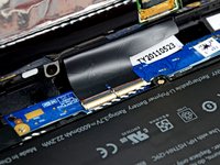
Use the edge of a plastic opening tool to peel up the two pieces of copper tape covering the USB connector board near the battery and the motherboard.
-
-
-
Remove the four 3.2 mm Phillips screws securing the USB connector board to the rear case.
-
-
-
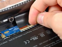
Pry the upper end of the USB connector board upwards to disconnect it from its socket on the logic board.
-
-
-
Pull the USB connector board away from the bottom edge of the rear case and lift, but do not remove it out of its housing.
-
-
-
Pull the vibrator motor connector straight away from its socket on the USB connector board.
-
Remove the USB connector board from the TouchPad.
-
NOTE: First verify that there is a connector before pulling! The vibrator motor may be soldered directly to the USB Board requiring the motor to be pried up and removed together with the board.
This piece may be soldered. If that is the case, just leave it connected and move the USB connector board aside
-
-
-
Use the edge of a plastic opening tool to flip up the retaining flap on the volume control/power button ribbon cable socket.
-
Pull the cable out of its socket.
-
-
-
Use a plastic opening tool to lift the camera connector up and out of its socket on the motherboard.
-
Bend the camera cable away from the motherboard.
-
-
-
Carefully flip up the retaining flap on the microphone cable socket.
-
Pull the microphone cable out of its socket.
Its just a reminder when you're repairing your touchpad back to the way it was ( reversing the steps) It might be difficult to place your microphone ribbon back into its socket. Would advise to use some sort of device ( like tweezers) to help place it back inside its socket. Just be gentle.
-
-
-
Use your plastic opening tool to pry the upper antenna connector up from its socket on the motherboard.
-
-
-
Pry up the retaining flap on the headphone jack ribbon cable socket.
-
Pull the headphone jack ribbon cable out of its socket.
-
-
-
Pry the speaker cable connector up from its socket on the motherboard.
-
-
-
Use a plastic opening tool to flip up the retaining flap on the digitizer board ribbon cable socket.
-
Pull the digitizer ribbon cable out of its socket.
-
-
-
Pry up the lower antenna cable connector from its socket on the motherboard.
-
-
-
De-route the lower antenna cable along the top edge of the battery and carefully pull it out from under its retaining clip near the top right corner of the battery.
-
-
-
Remove the eight 3.2 mm Phillips screws securing both the battery and the motherboard to the rear case.
-
-
-
Use a plastic opening tool to pry the battery up from the tape securing it to the rear case.
The battery may be tightly adhered to the copper foil beneath. Take care not to damage this foil or the battery charging coil beneath it.
-
-
-
Lift the motherboard assembly out of the rear case, minding any cables that may get caught.
-
-
-
Carefully pull the battery away from the L-shaped motherboard to disconnect its cable.
-
Remove the battery from the motherboard.
-
-
-
Battery remains.
Great Photos! My battery is completely dead, so now I'm going to order a new one. Would love to find a writeup on hoiw to shock this old battery back to life while out of the computer. Any suggestions?
This is not an easy exercise. There are numerous small parts and connectors. Even stuff I could see I broke.
-


To reassemble your device, follow these instructions in reverse order.
To reassemble your device, follow these instructions in reverse order.
crwdns2935221:0crwdne2935221:0
crwdns2935229:058crwdne2935229:0

crwdns2947412:08crwdne2947412:0
Removing the screen is easily the most difficult, time consuming and frustrating part of the whole process. Once removed, the rest, while tedious, is not particularly difficult.
Replaced the battery, and still not powering up. Is there some sort of step missing to activate the battery? I have two devices which has the same issue, and can't power them up again after replacing the battery which is fully charged.
A little late, but you can Google:
tpdebrick-v004
Procedure to slap everything back into a slightly corrupted touchpad so it will start taking a charge if not below critical voltage.
Is this worth bothering with? An Amazon Fire HD 8 is $80.
Very well done! I could have used a little more “here is a clip that holds the screen frame to the body frame…” because I was gently prying the screen out of its own frame. But luckily never snapped it.
i have 2 units, 1 of which went below battery critical and is in that protective state now where it won’t take a charge. Going to take the battery from the other unit so I can power this one on and the flash the battery system firmware to reset and hopefully initiate the charging capabilities.
i honestly can’t believe this was built back in 2011 because they did a pretty good job.
And I just happened to see an original charging barrel at my friends house while visiting in another state. He was just charging his iPhone with it so I begged him to trade me for a wall wart that I had. Super lucky find.
thanks again for posting this guide.
And to anyone still reading, the newest nightly builds will crash your touchpad for sure.
Written 4/3/2019
james
The newest nightly builds? I thought HP had totally abandoned the TouchPad.
The HP Touch Pad battery has two cells in parallel attached to a protection circuit board. These protection circuits will shut down the battery if the cell voltage drops below 2.8 VDC. On one old unit I managed to reach the direct cell contacts and they were below 2 VDC. I will try to recharge each cell individually and see if the protection circuit will reactivate, allowing power to flow through the connector.
Dude let me tell you i had this exact model, and the battery was a pillow and these instructions are on par, Thank you!!
Beware of the ribbon cable right beneath the volume rocker, as it's easy to shear that cable if you are too rough with the metal spudger.
Michael Innes - crwdns2934203:0crwdne2934203:0
I wasn’t happy with using a metal spudger as it felt a bit forceful, as I have a bulk pack of opening tools I tried using them instead.
I may have been lucky, but by using those tools instead with the angled lip facing inwards at points adjacent to where the mounting clips are located according to the above image (like this, https://i.imgur.com/dylp6BG.jpg ), I managed to open the unit without breaking a clip or scratching the plastic back panel by bending the outside of the panel enough to pop the lcd panel.
Michael Sim - crwdns2934203:0crwdne2934203:0