crwdns2915892:0crwdne2915892:0
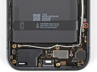
This guide shows how to remove the vibration motor in your Google Pixel 9a smartphone.
crwdns2942213:0crwdne2942213:0
-
-
Unplug all cables and completely power down your phone.
-
-
-
Firmly press a SIM eject tool, bit, or straightened paper clip into the SIM card tray hole on the bottom edge of your phone until the tray ejects.
-
Remove the SIM card tray.
-
-
-
Use a hair dryer to heat the entire rear cover.
-
-
-
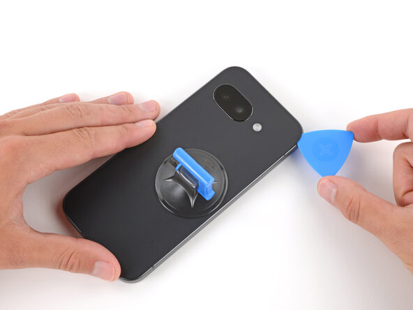
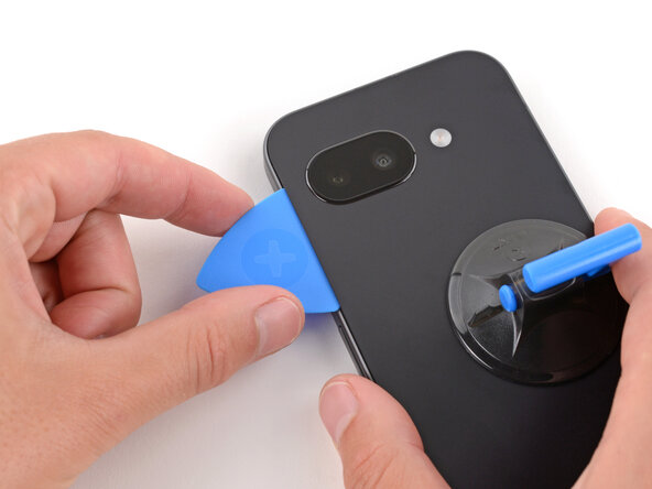
Apply a suction handle near the center of the rear cover's right edge, as close to the edge as possible.
-
-
-
Pull up on the suction handle with strong, steady force until a gap forms between the cover and frame.
-
Insert the tip of an opening pick into the gap.
-
-
-
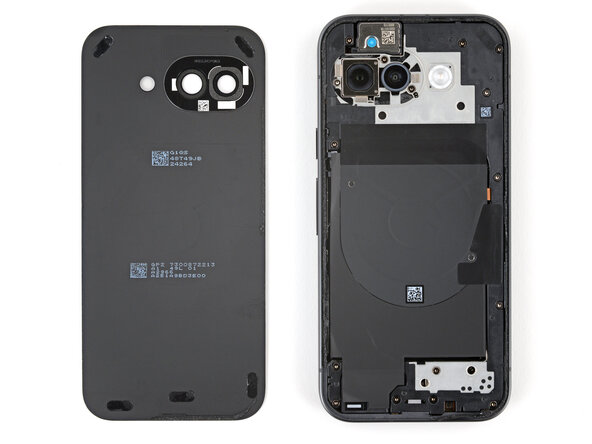
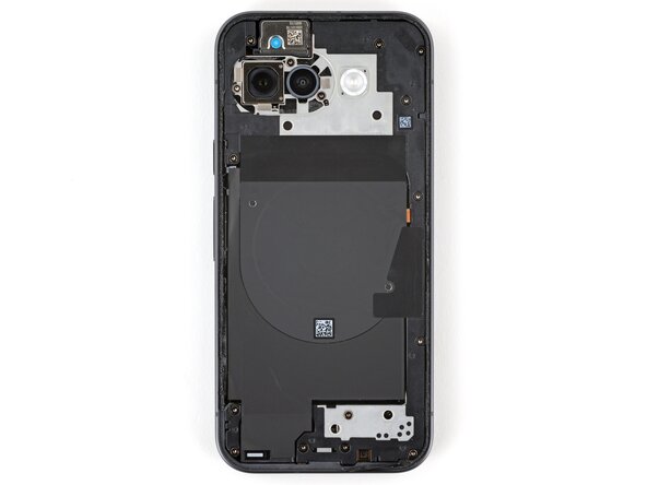
The rear cover is secured with adhesive around the perimeter of the frame and near the cameras. Use this picture as a reference while you separate the adhesive.
-
-
-
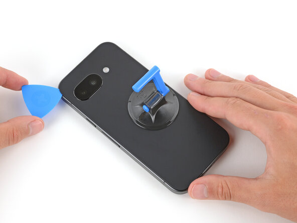
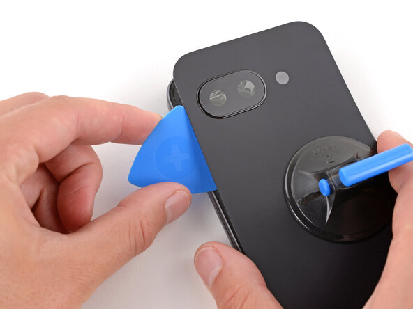
Slide the opening pick up the right edge, around the top right corner, and along the top edge to separate the adhesive securing the rear cover.
-
-
-
Insert an opening pick in the initial gap you created near the center of the rear cover's right edge.
-
Slide the opening pick down the right edge, along the bottom edge, and up the left edge to separate the adhesive securing the cover.
-
-
-
Insert the flat edge of an opening pick under the top of the rear cover's left edge, near the camera bezel.
-
Twist the pick and apply constant pressure to separate the adhesive around the camera bezel.
-
-
-
Remove the rear cover.
-
-
-
-
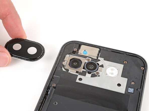
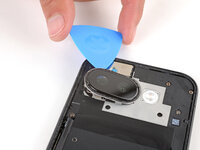
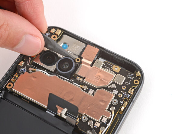
Slide an opening pick under the camera bezel and pry up to remove it.
-
-
crwdns2935267:0crwdne2935267:0Magnetic Project Mat$19.95
-
Use a Torx Plus 3IP screwdriver to remove the 16 screws securing the wireless charging assembly:
-
Thirteen 5.0 mm‑long screws
-
Three 2.2 mm‑long screws
-
Throughout this repair, keep track of each screw and make sure it goes back exactly where it came from to avoid damaging your phone.
-
-
-
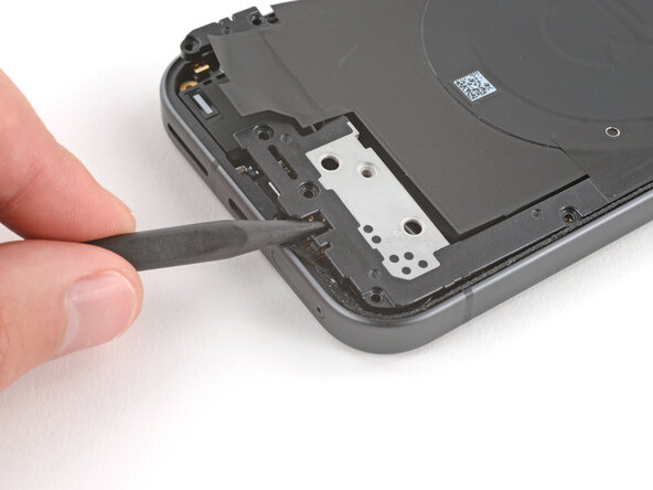
Use the point of a spudger to pry up and unclip the wireless charging assembly from the two cutouts—one to the right of the charge port, and another on the left edge just below the camera.
-
-
-
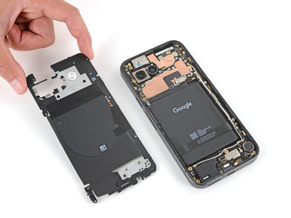
Remove the wireless charging assembly.
-
-
-
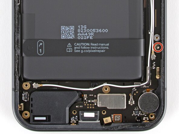
Use a Torx Plus 3IP screwdriver to remove the 1.7 mm‑long screw securing the battery connector cover.
-
-
-
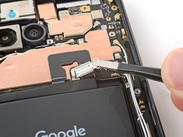
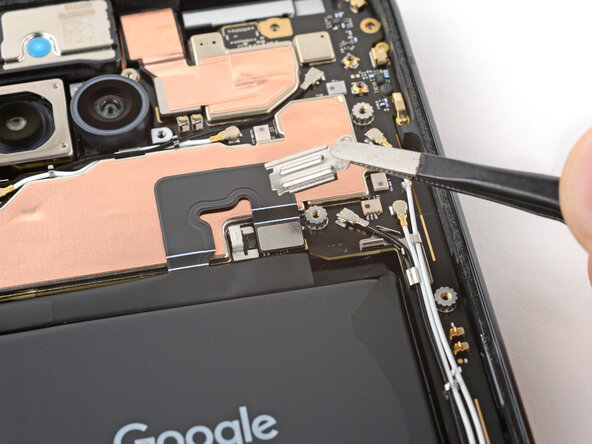
Use tweezers to lift and remove the battery connector cover.
-
-
-
Use a spudger to pry up and disconnect the battery cable press connector.
-
-
-
Use a 3IP Torx Plus screwdriver to remove the two 2.8 mm‑long screws securing the logic board.
-
-
-
Insert the point of a spudger under the screw hole near the cameras and lift the board until you can grip it with your fingers.
-
-
-
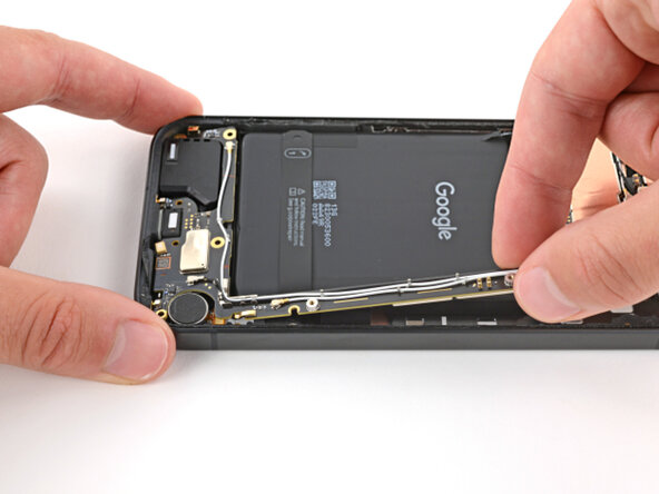
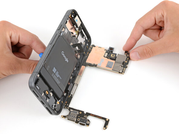
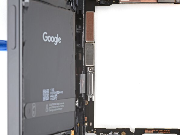
Grip the skinny section of the board with your fingers and lift until the clip near the bottom edge of the battery releases.
-
Pull the top edge of the board to the right of the frame until the charge port slides fully out of its recess.
-
-
-
Apply a suction handle to the screen and use it to prop up your phone.
-
Gently lay the logic board down flat against your work surface, being careful not to strain the screen cable.
-
-
-
Use a Torx Plus 3IP screwdriver to remove the 1.7 mm‑long screw securing the screen cable cover.
-
-
-
Use tweezers to lift and remove the screen cable cover.
-
-
-
Use the flat end of a spudger to pry up and disconnect the screen cable press connector.
-
-
-
Slide the logic board away from the frame and remove it.
-
-
-
Remove the suction handle from the screen and lay your phone down.
-
-
-
Lift the left side of your phone and apply 1–2 drops of high-concentration (>90%) isopropyl alcohol to the left edge of the vibration motor.
-
Keep your phone lifted and wait one minute for the isopropyl alcohol to soften the adhesive securing the vibration motor.
-
-
-
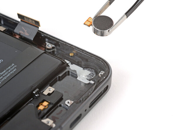
Use the flat end of a spudger to pry up the vibration motor by its right edge.
-
Remove the vibration motor.
-


