crwdns2915892:0crwdne2915892:0
Congratulations on getting the Framework Laptop 16 DIY Edition! Follow this quick start guide to assemble your laptop and get it running.
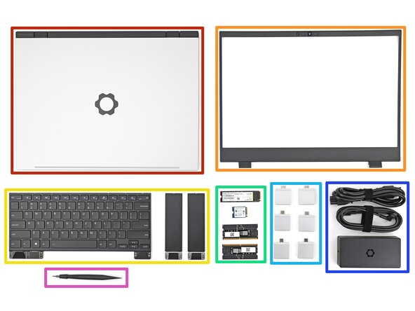
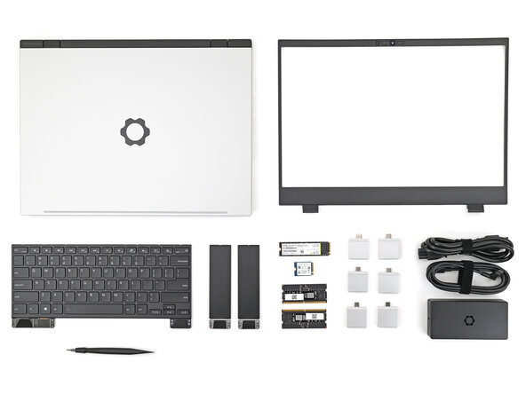
crwdns2942213:0crwdne2942213:0
-
-
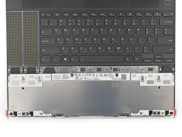
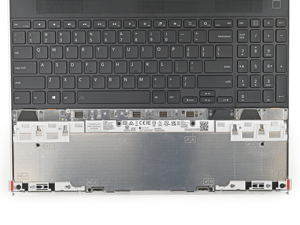
Framework Laptop chassis with pre-installed Mid Plate, Touchpad Module, and Touch Spacers.
-
Bezel
-
Keyboard and Input Modules
-
Memory and Storage
-
Expansion Cards
-
Power Adapter
-
Framework Screwdriver
-
-
-
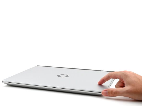
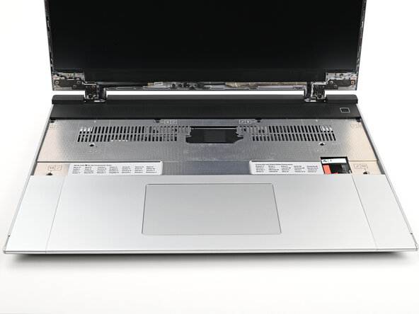
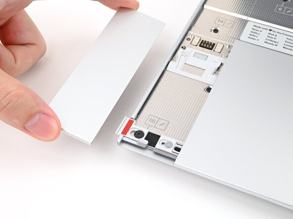
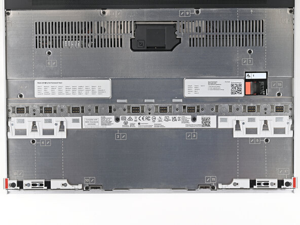
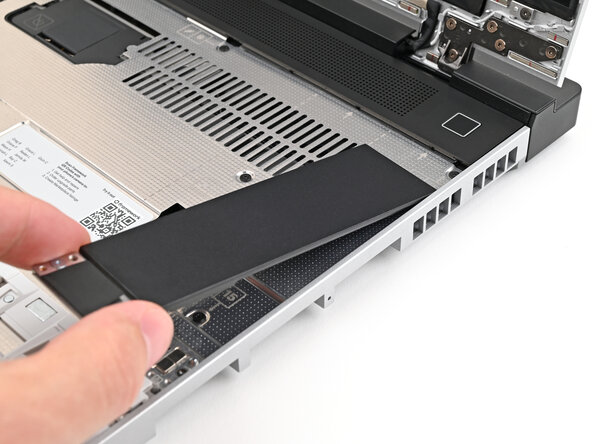
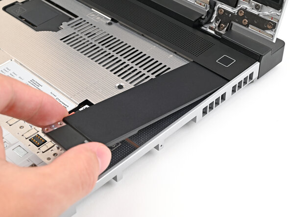
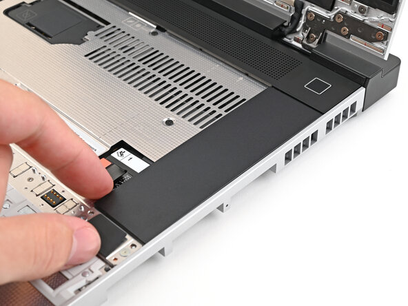
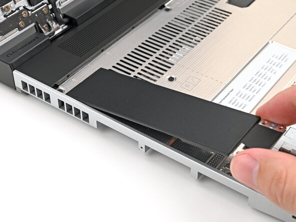
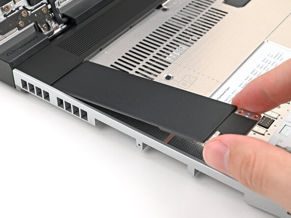
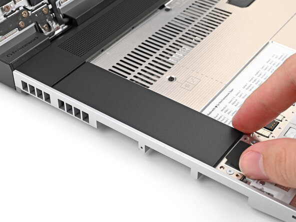
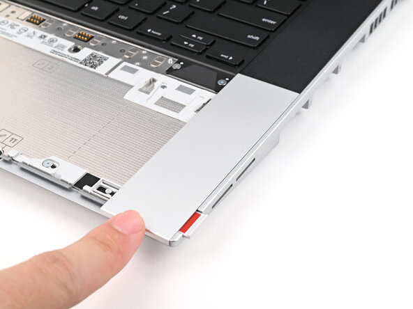
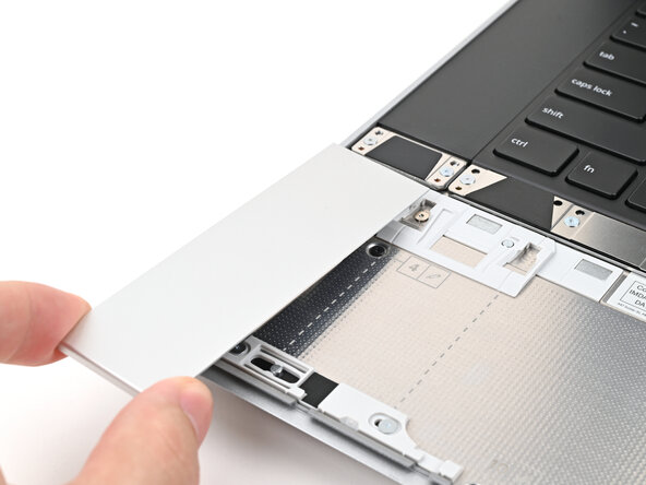
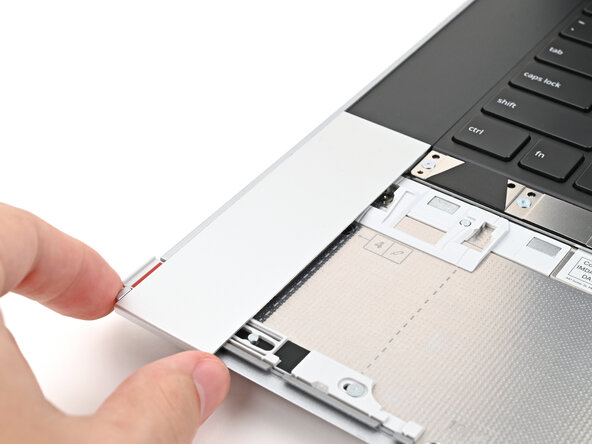
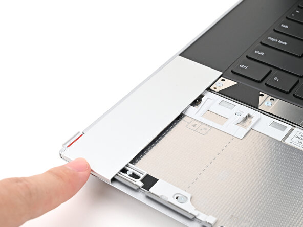
Remove the plastic cover.
-
-
-
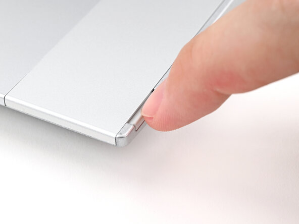
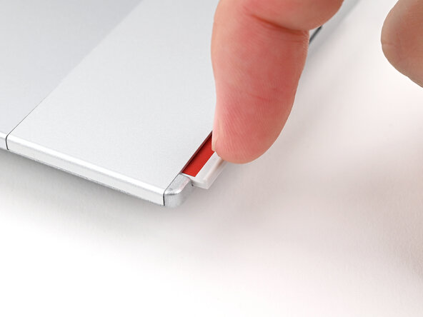
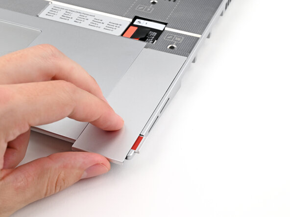
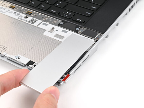
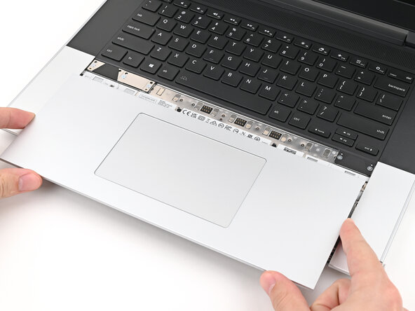
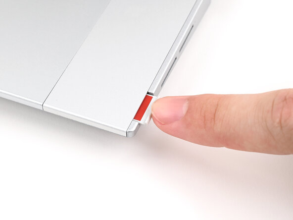
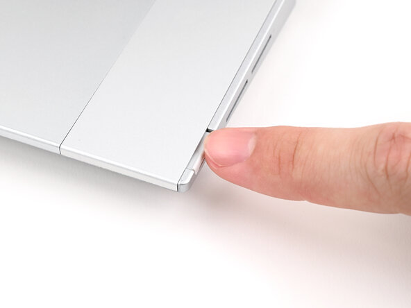
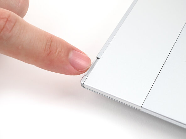
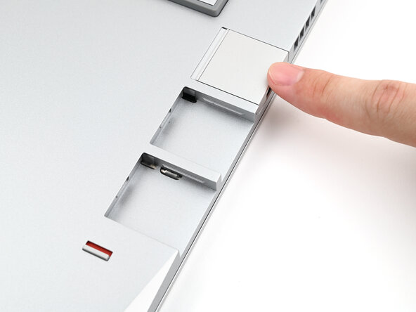
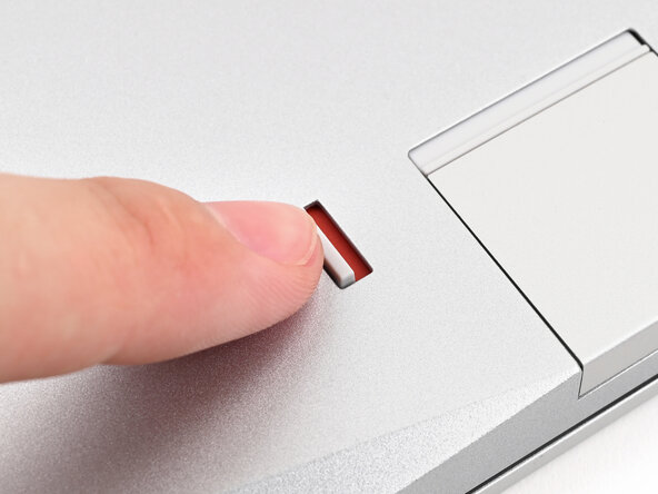
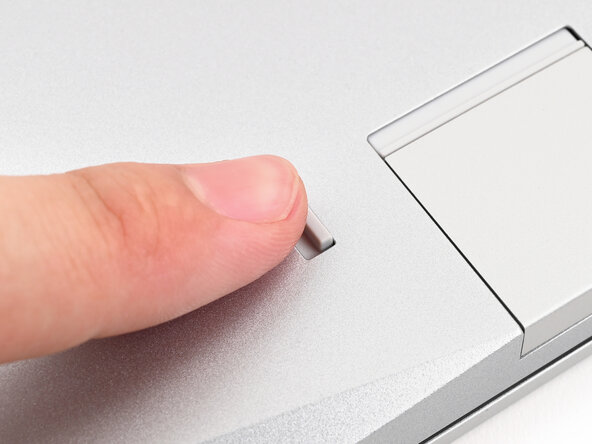
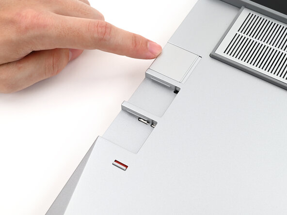
Use your fingernail to pull out the Input Module latch and unlock the Touchpad Spacer next to it.
-
-
-
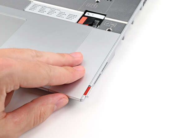
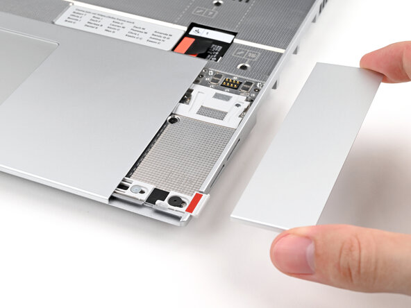
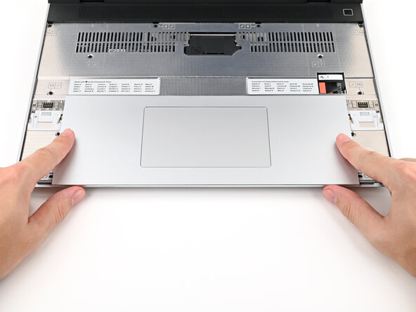
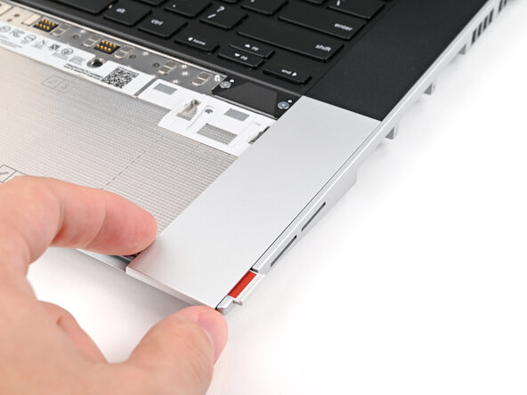
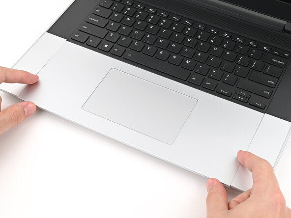
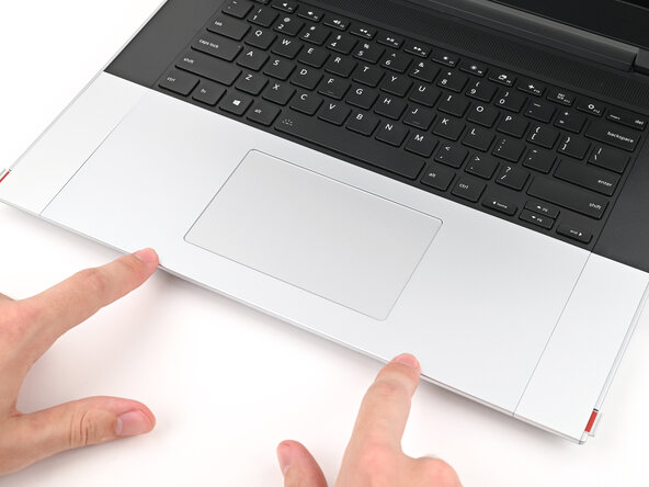
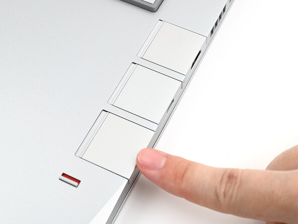
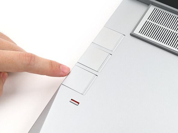
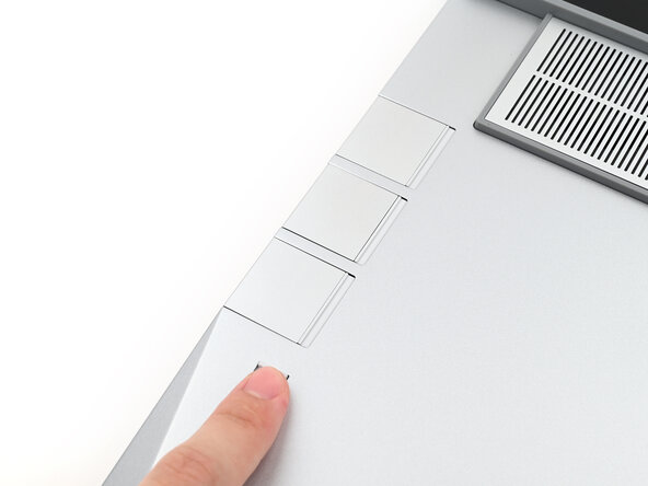
Use your fingers to slide the Touchpad Spacer toward the bottom edge of the laptop and unclip it.
-
Lift the Touchpad Spacer off the laptop and remove it.
-
-
-
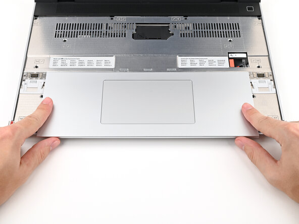
Repeat the previous two steps to remove the other Touchpad Spacer.
-
-
-
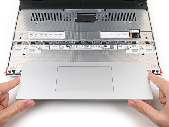
Use your fingers to slide the Touchpad Module toward the bottom edge of the laptop and disconnect it.
-
Lift the Touchpad Module and remove it.
-
-
-
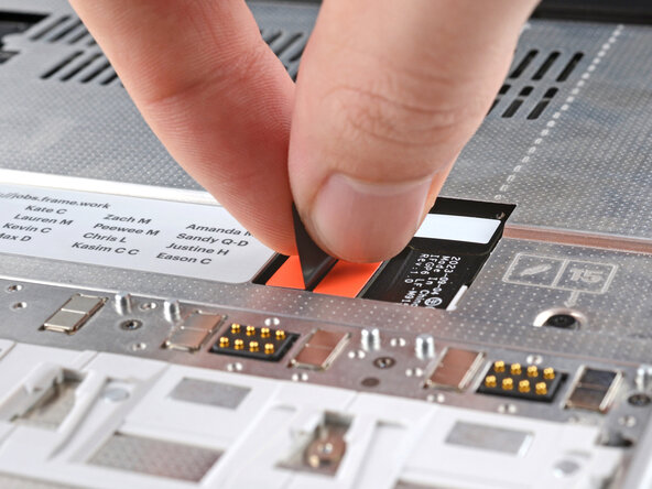
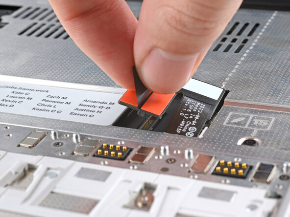
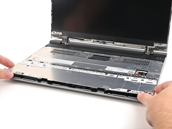
Grip the black pull tab on the Mid Plate cable press connector and lift up to disconnect it.
-
-
-
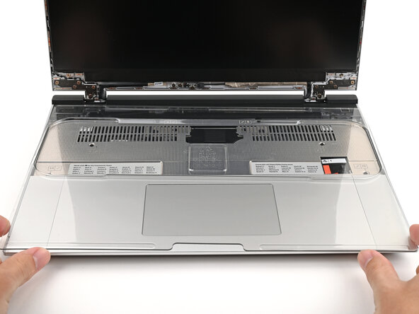
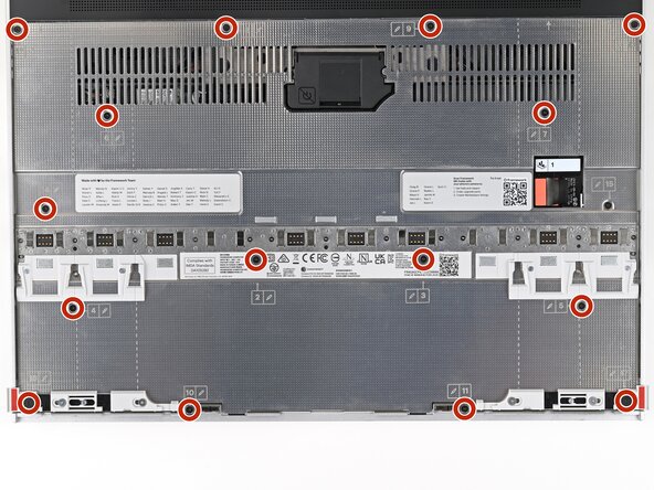
Use your Framework Screwdriver to loosen the 16 captive T5 Torx screws securing the Mid Plate.
-
-
-
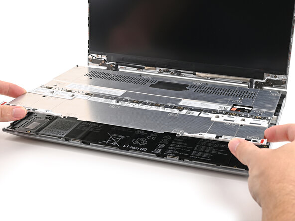
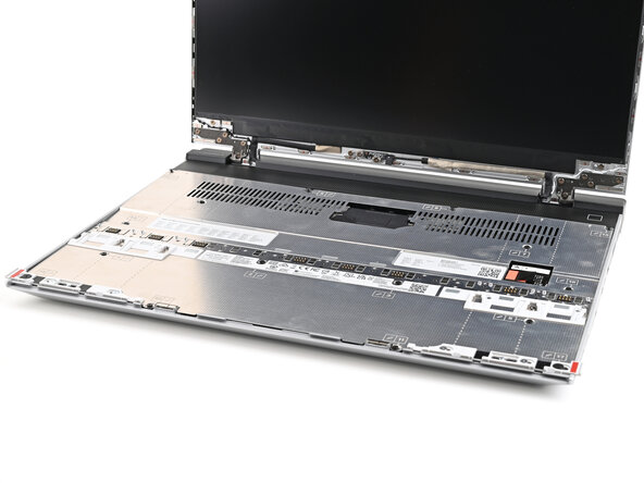
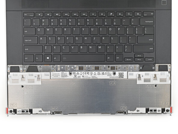
Use your fingers to lift the Mid Plate off the laptop and remove it.
-
-
-
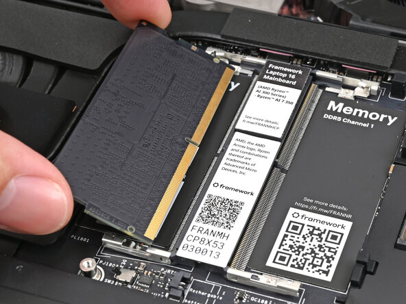
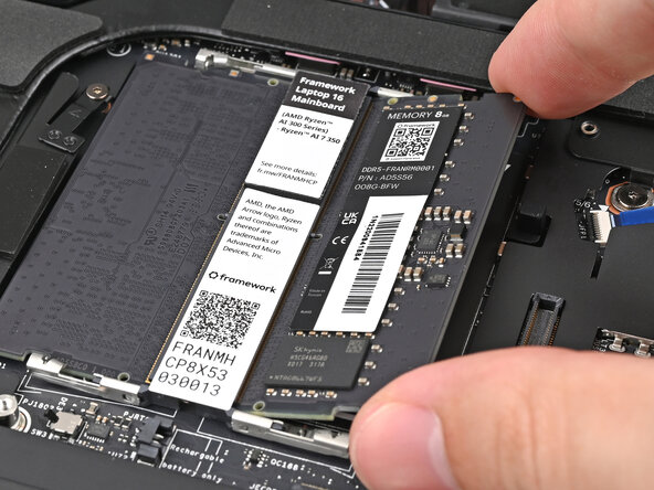
Orient the module with its label facing down and align the gold contacts with the left socket labeled DDR5 Channel 0.
-
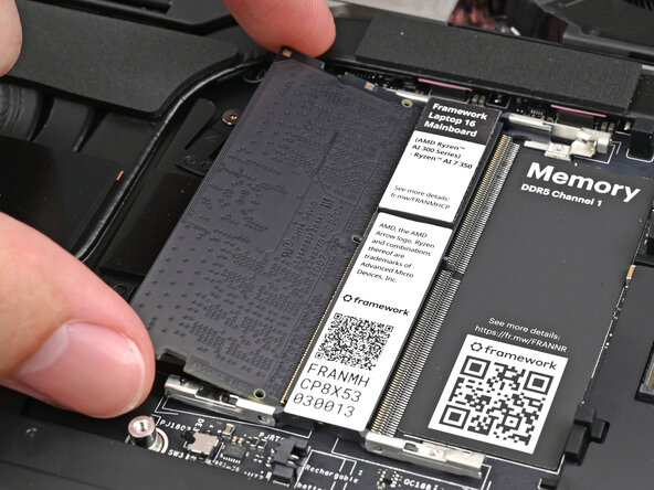
Insert the contact edge into the socket at a shallow angle. The gold contacts should mostly be covered by the socket.
-
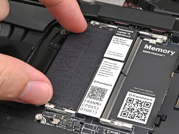
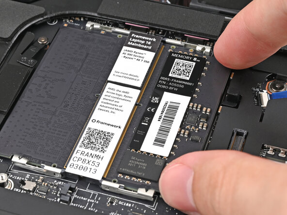
Press the edges of the memory module down until the side clips lock it in place.
-
-
-
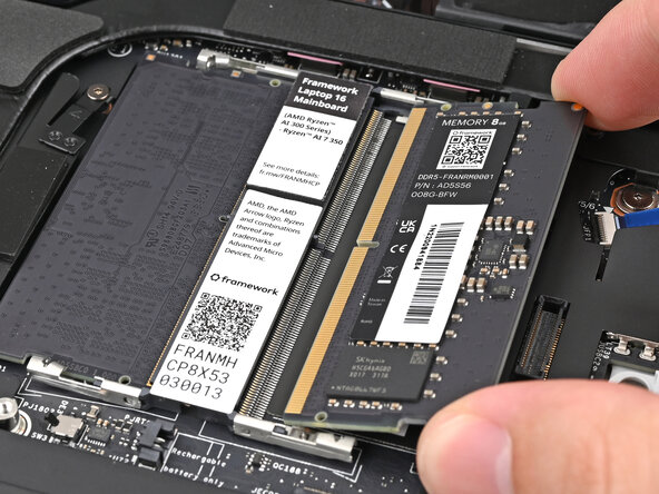
If you're using two memory modules, orient the other module so its label is facing upward and repeat the previous step for the other socket labeled DDR5 Channel 1.
-
-
-
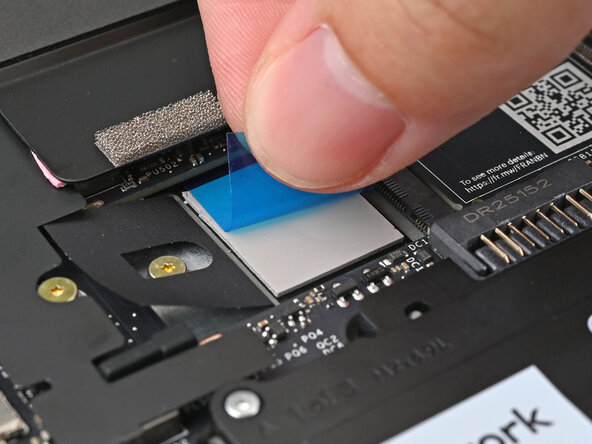
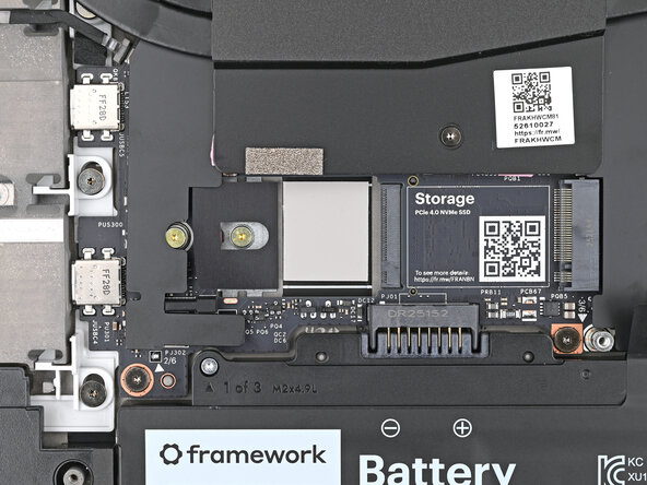
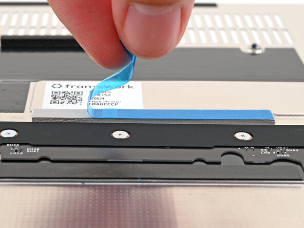
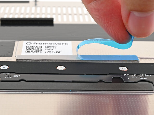
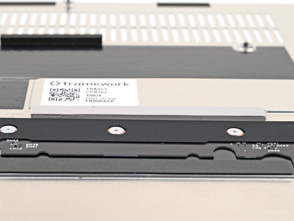
Remove the blue liner from the secondary SSD thermal pad.
-
-
-
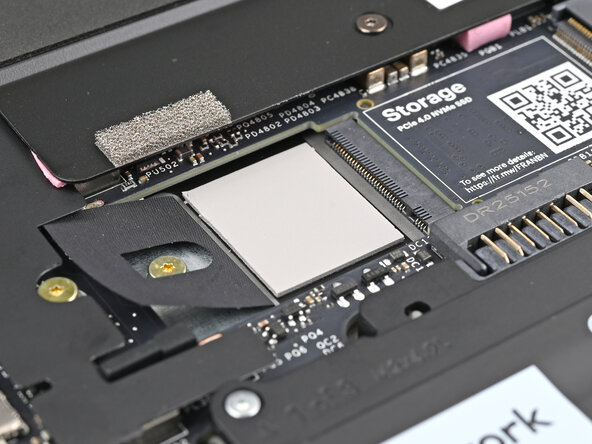
Use your Framework Screwdriver to remove the 2 mm‑long T5 Torx screw securing the secondary SSD.
-
-
-
-
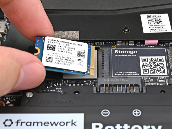
Align the SSD's gold contacts with its socket.
-
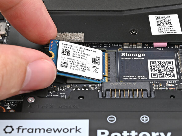
Insert the SSD partially into the socket at a shallow angle. You should still be able to see most of the gold contacts.
-
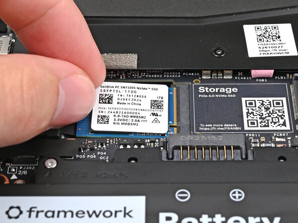
Press the SSD flat to the Mainboard.
-
-
-
While keeping the SSD flat to the Mainboard, use your finger to slide the SSD into its socket until its golden contacts are completely covered.
-
-
-
Use a Framework Screwdriver to install the 2 mm‑long T5 Torx screw securing the secondary SSD.
-
-
-
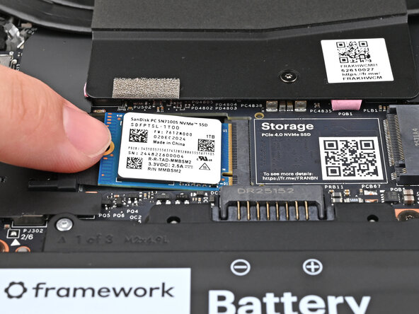
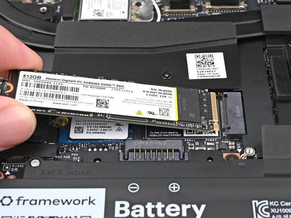
Use your Framework Screwdriver to remove the 2 mm‑long T5 Torx screw securing the primary SSD.
-
-
-
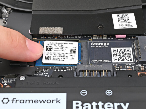
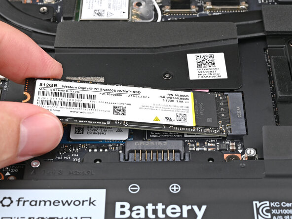
Insert the SSD into the socket at a shallow angle. The gold contacts should mostly be covered by the socket.
-
-
-
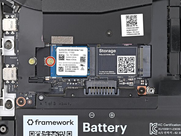
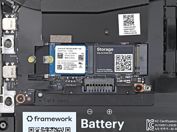
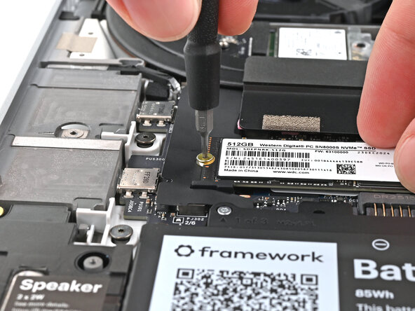
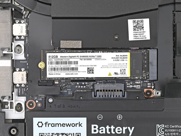
While holding the SSD flat to the Mainboard, use your Framework Screwdriver to install the 2 mm‑long T5 Torx screw securing the primary SSD.
-
-
-
If there's a blue liner on the thermal pad located on the bottom of the Mid Plate, use your fingers to peel it off.
-
-
-
Place the Mid Plate on the laptop, making sure it sits evenly on its alignment pegs.
-
-
-
Use your Framework Screwdriver to tighten the 16 T5 Torx captive screws in order (starting with 2) to secure the Mid Plate evenly.
-
-
-
Align the Mid Plate cable press connector over its socket and press down to connect it.
-
-
-
Hold the Input Module at a slight downward angle and align it with one of the dotted lines on the Mid Plate.
-
Slide the top lip of the Input Module underneath the ventilation plate and lay the module down flat to let the magnets pull it into place.
-
-
-
Repeat the previous step for the other Input Module.
-
-
-
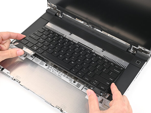
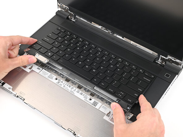
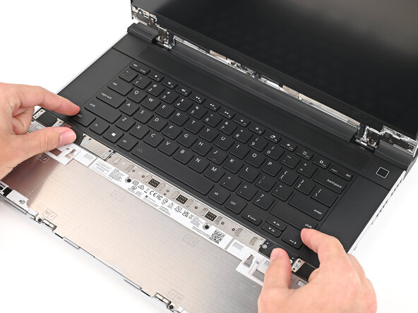
Hold the keyboard at a slight downward angle and align it with two of the dotted lines on the Mid Plate.
-
Slide the top lip of the keyboard underneath the ventilation plate and lay the keyboard down flat to let the magnets pull it into place.
-
-
-
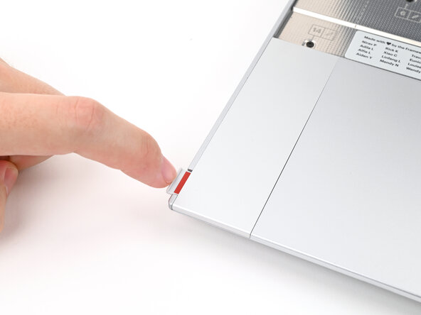
Place the Touchpad Spacer over its spot on the laptop with the bottom edge overhanging slightly.
-
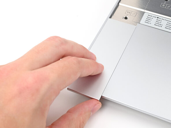
Slide the Touchpad Spacer towards the top of the laptop to secure it.
-
-
-
Repeat the previous step for the other Touchpad Spacer.
-
-
-
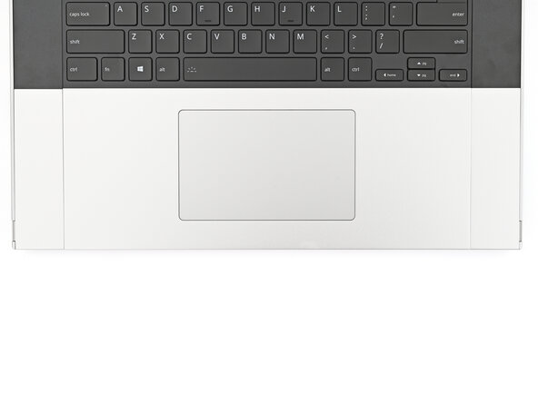
Place the Touchpad Module flat on its cutout so its clips are properly aligned.
-
Press the Touchpad Module down and slide it into place so it lines up evenly with the bottom edge of the laptop.
-
-
-
Push the Input Module latches back into place to lock them.
-
-
-
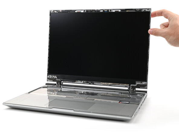
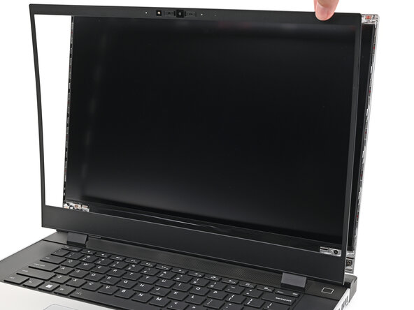
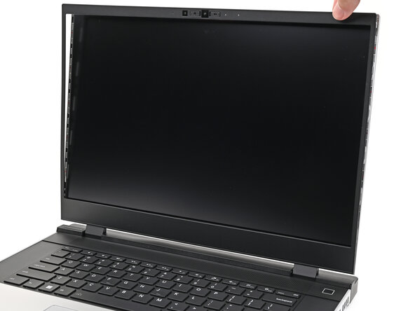
Align the bezel over the perimeter of the display and let the magnets pull the bezel into place.
-
-
-
Close the laptop and flip it over.
-
-
-
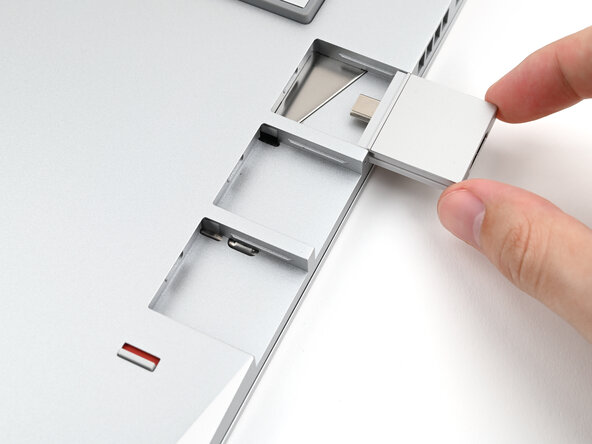
Slide an Expansion Card into an Expansion Card slot.
-
Repeat for the remaining Expansion Cards along that edge.
-
-
-
If there's a red bar showing under the Expansion Card latch, use your finger to flip the latch and lock the row of Expansion Cards above it.
-
-
-
Repeat the previous two steps for the other row of Expansion Cards.
-
-
-
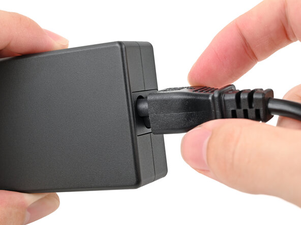
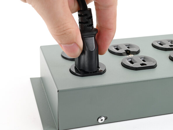
Plug the AC Cable into the Power Adapter.
-
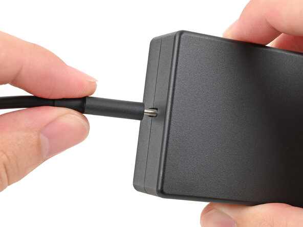
Plug the USB-C Cable into the Power Adapter.
-
Plug the AC Cable into a power outlet.
-
-
-
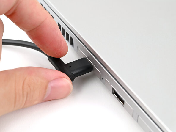
Your Framework Laptop ships in shipping mode, where the battery is disabled until you plug the laptop in for the first time.
-
Plug the USB-C Cable into any USB-C port on your laptop.
-
-
-
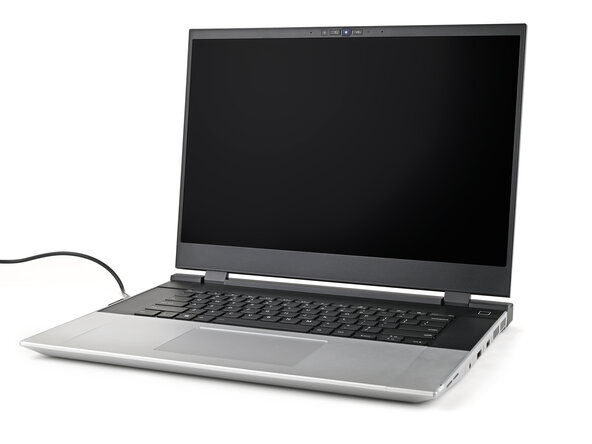
You're done assembling your Framework Laptop! Now, you'll need to install an OS.
-


For drivers, firmware, and software updates, check out this page.
If you need help, contact Framework support.
For drivers, firmware, and software updates, check out this page.
If you need help, contact Framework support.
