crwdns2915892:0crwdne2915892:0
Follow this guide to remove and replace the display in your Framework Laptop 12.
The display (aka display panel or screen) is the LCD panel in your laptop. The display also has the touchscreen and stylus functionality built into the part. If you crack your display or if the touchscreen doesn't work, you may need to replace this part.
You'll encounter some component terms in this guide:
- The Display Cover is the plastic bezel strip below the display.
- The Top Cover is the plastic shell that houses the display.
crwdns2942213:0crwdne2942213:0
-
-
Before you begin repairs, unplug your laptop and shut it down from the operating system. This ensures that the laptop isn't in standby/suspend mode.
-
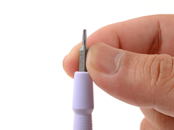
Make sure your Framework Screwdriver has the T5 Torx bit (labeled as T-5) facing outwards. If it's not, pull the bit out and flip it.
-
-
-
Open the laptop lid so that both the screen and the base lie flat on your work surface.
-
-
-
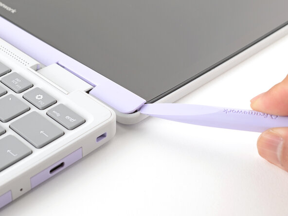
Use the flat end of your Framework Screwdriver to pry up the right edge of the Display Cover.
-
-
-
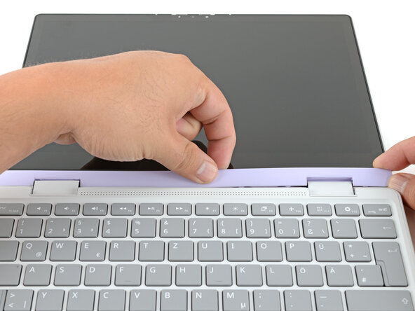
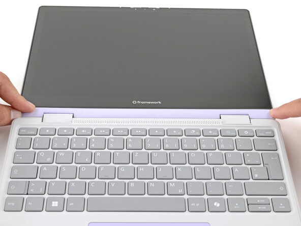
Slide your fingers under the top edge of the Display Cover to release it from the laptop.
-
-
-
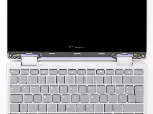
Use your Framework Screwdriver to remove the four 3.3 mm‑long T5 Torx screws securing the display to the Top Cover.
-
-
-
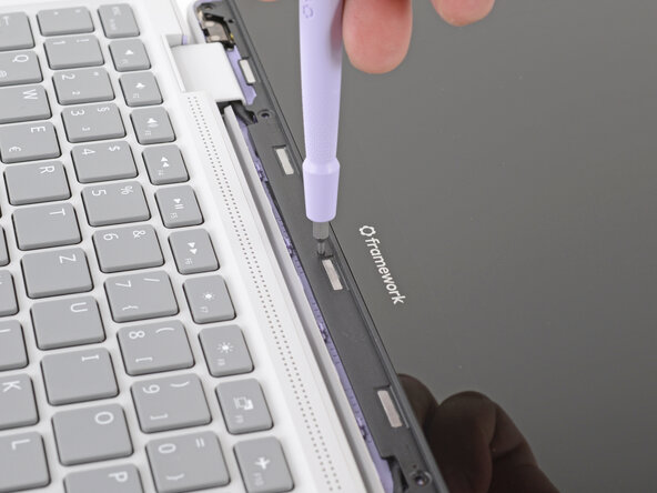
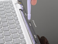
Insert the bit end of your Framework Screwdriver into the small hole on the display, below the Framework logo.
-
Slide the display down towards the hinge edge to release the tabs holding the top edge of the display in place.
-
-
-
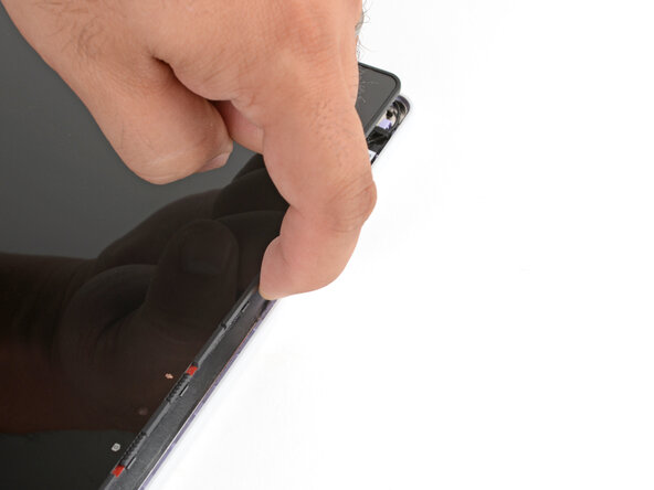
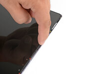
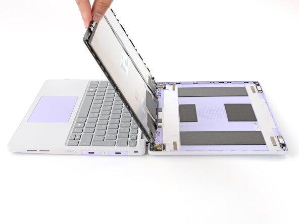
Use your fingers to lift the top edge of the display from the Top Cover.
-
-
-
Use your fingers to carefully swing the display over so it lies on top of the keyboard.
-
-
-
Use your Framework Screwdriver to remove the two 3.3 mm‑long T5 Torx screws securing the webcam bracket on the top edge behind the display.
-
-
-
Use the flat end of your Framework Screwdriver to lift the webcam out of its recess.
-
Flip the webcam over and gently hold it down with your fingers.
-
-
-
Use the flat end of your Framework Screwdriver or a fingernail to gently pry up the locking tab on the webcam cable ZIF connector.
-
-
-
-
Slide the webcam cable out of its connector.
-
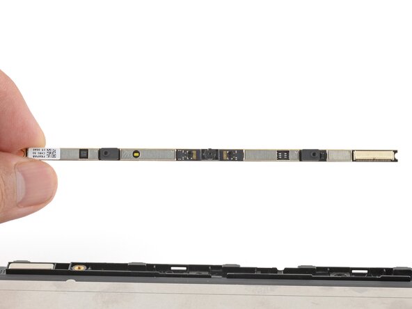
Remove the webcam.
-
-
-
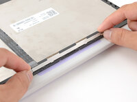
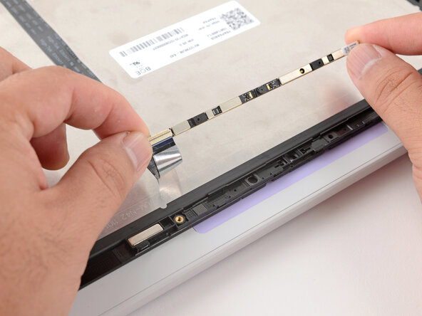
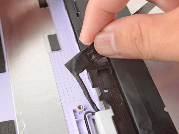
Grab the webcam cable with your fingers and slowly peel it away from the display.
-
Carefully move the cable off of the display.
-
-
-
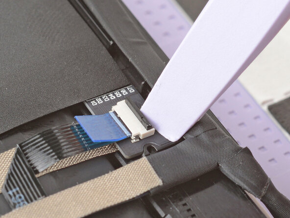
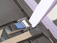
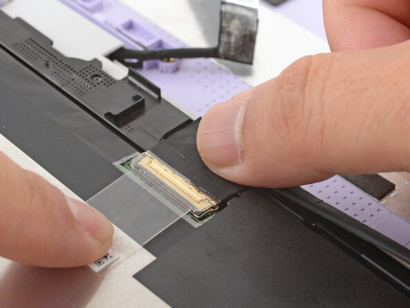
Use the flat end of your Framework Screwdriver or a fingernail to gently pry up the locking tab on the touch control ZIF connector near the hinge edge of the display.
-
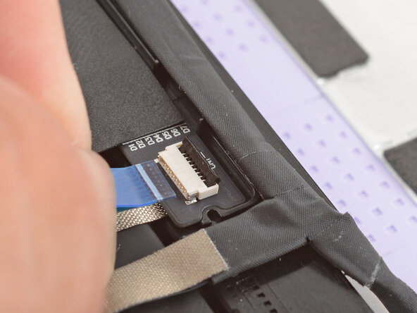
Use your fingers to grab the touch control cable by the blue tab and slide the cable out of the connector.
-
-
-
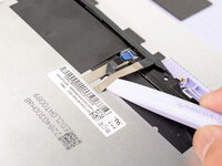
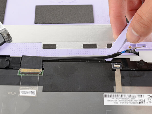
Slide the flat end of your Framework Screwdriver under the grounding tape securing the display cable.
-
Lift slowly to separate the tape from the display.
-
-
-
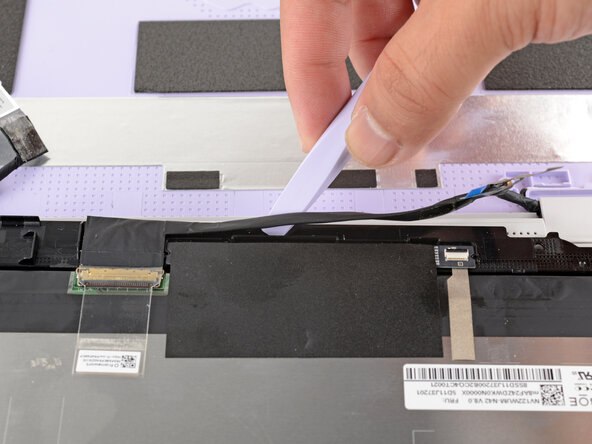
Slide the flat end of your Framework Screwdriver under the length of the display cable to separate it from the display.
-
-
-
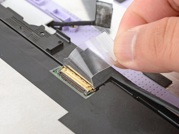
Use your fingers to peel up the clear tab covering the display cable connector.
-
-
-
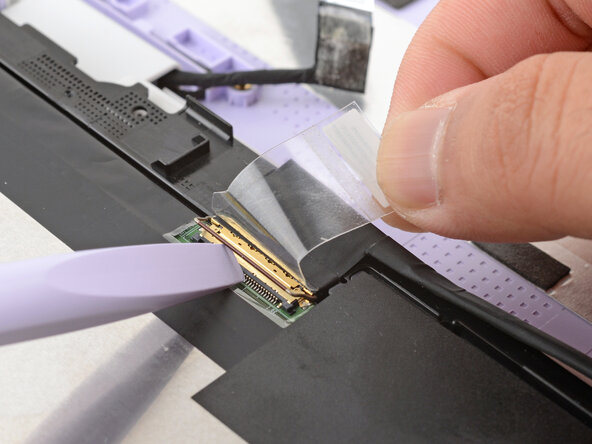
Use the flat end of your Framework Screwdriver to flip up the locking bar around the display connector.
-
-
-
Grasp the display cable near the connector and slide it out of the connector.
-
-
-
Carefully lift and remove the display.
-
-
-
Inspect the replacement display and carefully peel off any protective liners.
-
Use your Framework Screwdriver to remove the two 3.3 mm‑long T5 Torx screws securing the webcam bracket on the replacement display.
-
Remove the webcam bracket.
-
Remove any protective liners that may be in the webcam recess. The liners are normally clear or colored plastic films that easily detach.
-
-
-
Carefully lay the display screen-side down on top of the Input Cover. The edge with the webcam should lay near the touchpad edge.
-
Use your fingers to slide the display off the Input Cover magnets towards the hinge edge so that the display cable can reach its connector.
-
-
-
Use your fingers to grab the display cable by the clear tab and the locking bar.
-
Align the display cable with its connector and slide it in until it's fully seated.
-
-
-
Swing the locking bar down over the connector.
-
Lay the clear tab over the connector and press it onto the display.
-
-
-
Slide the touch control cable into the ZIF connector up to the printed line on the cable.
-
Use your finger to flip down and gently press the locking tab in place.
-
-
-
Use your finger to press the display cable grounding tape onto the metal back of the display.
-
Use your fingers to press the display cable onto the display.
-
-
-
Use your fingers to press the webcam cable onto the display.
-
-
-
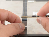
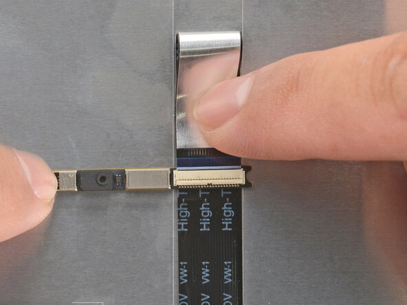
Bend an inch (2.5 cm) of the webcam cable over so that the shiny side is facing you.
-
Slide the webcam cable into the ZIF connector up to the printed line on the cable.
-
Use your finger to flip down and gently press the locking tab in place.
-
-
-
Use your fingers to flip the webcam back into its recess in the Top Cover.
-
-
-
Align the webcam bracket to the Top Cover and lay it in place.
-
Make sure the tabs on the top edge of the webcam bracket sit in their slots on the top edge of the display.
-
-
-
Use your Framework Screwdriver to install the two 3.3 mm‑long T5 Torx screws to secure the webcam.
-
-
-
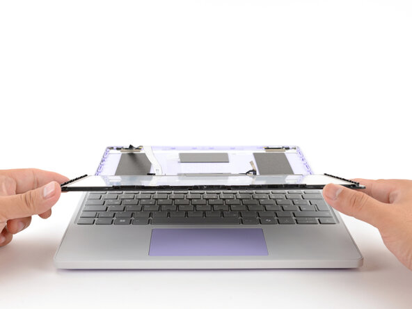
Use your fingers to carefully swing the display over so it lies on top of the Top Cover.
-
-
-
Align the display in the Top Cover such that the top edge of the display is slightly below the top edge of the Top Cover.
-
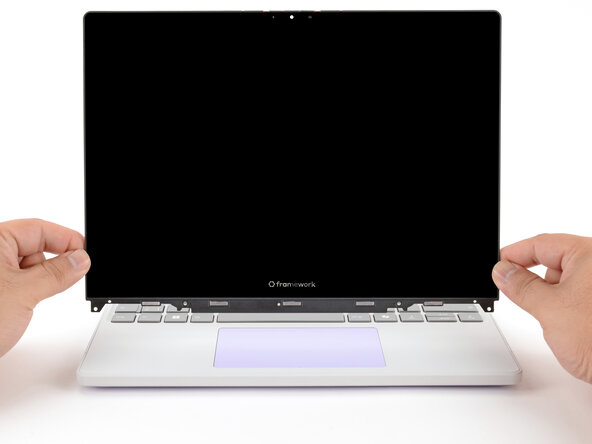
Use your fingers to slide the display upwards to latch the tabs on the top edge of the display.
-
-
-
Use your Framework Screwdriver to install the four 3.3 mm‑long T5 Torx screws to secure the display to the Top Cover.
-
-
-
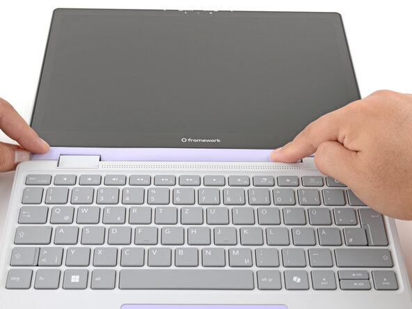
Align the Display Cover to the bottom of the display.
-
-
-
Use your finger to press along the length of the Display Cover to snap it onto the laptop.
-


You finished fixing your Framework Laptop!
Take your e-waste to an R2 or e-Stewards certified recycler.
If you need help, contact Framework support.

crwdns2935287:0crwdne2935287:0

Guide Team crwdns2935289:0Guide Teamcrwdne2935289:0
Staff
crwdns2931471:010crwdne2931471:0
crwdns2935297:017.771crwdne2935297:0