crwdns2915892:0crwdne2915892:0
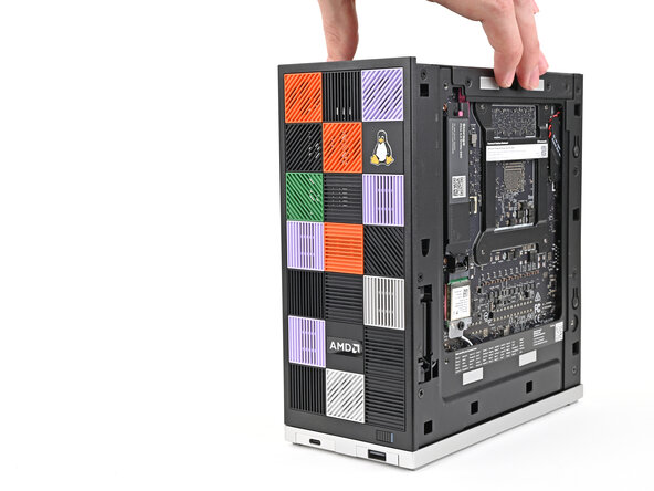
Follow this guide to remove and replace the Mainboard in your Framework Desktop.
Replacement Mainboards don't come with pre-installed storage, fans, or Wi-Fi modules. This guide will show how to transfer them to your new Mainboard.
If you're running Windows:
- Make sure you back up your data.
- If you’re running a Pro version of Windows, follow these directions to suspend BitLocker.
- If you're running a Home version of Windows and have enabled Windows Device Encryption, you'll want to disable it. To disable it, press Win + I to open Settings and select Privacy & Security. Then, click on Device Encryption on the right panel and toggle the setting to Off.
- Find your product key or link your Windows license to a Microsoft account to make sure you can re‑activate Windows after the change.
crwdns2942213:0crwdne2942213:0
-
-
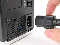
Before you begin repairs, shut down your Desktop from the operating system and unplug it.
-
Wait one minute before continuing to allow your Desktop to fully power down.
-
-
-
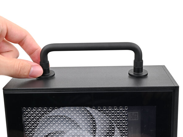
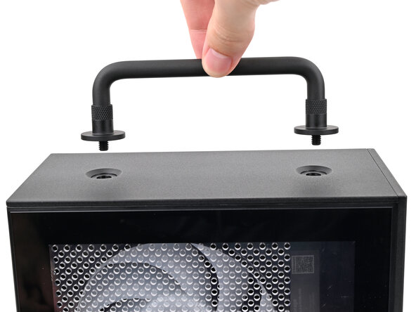
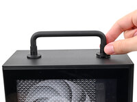
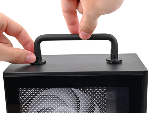
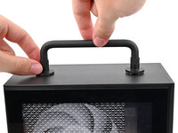
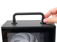
Rotate the Handle's screw threads counterclockwise on both sides until it comes free.
-
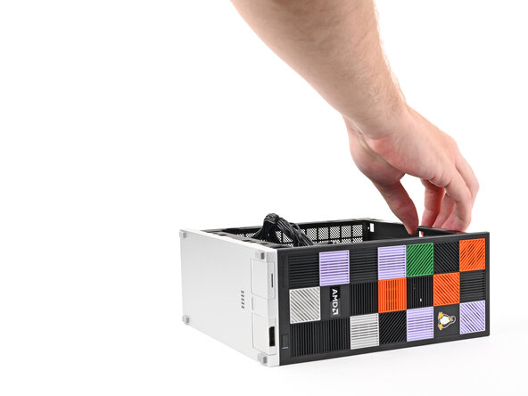
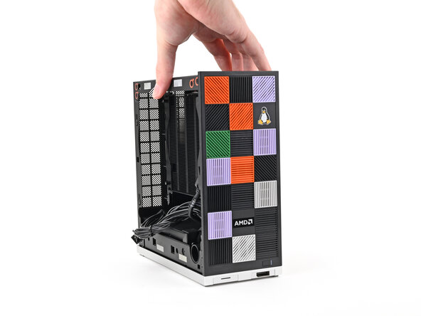
Remove the Handle.
-
-
-
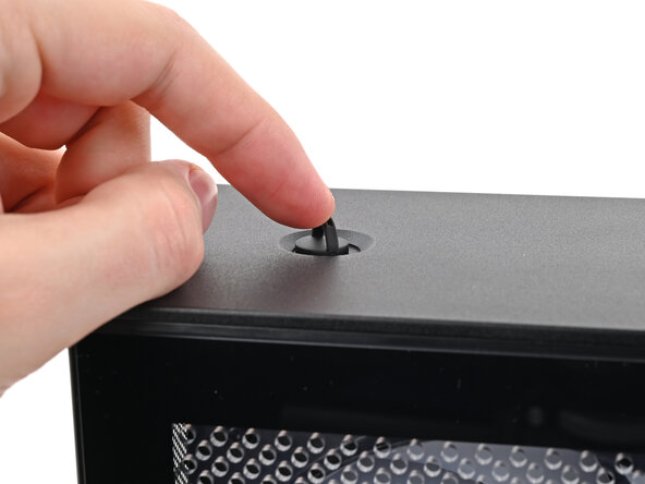
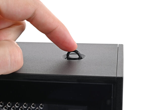
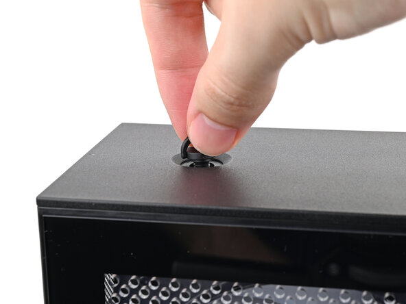
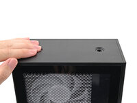
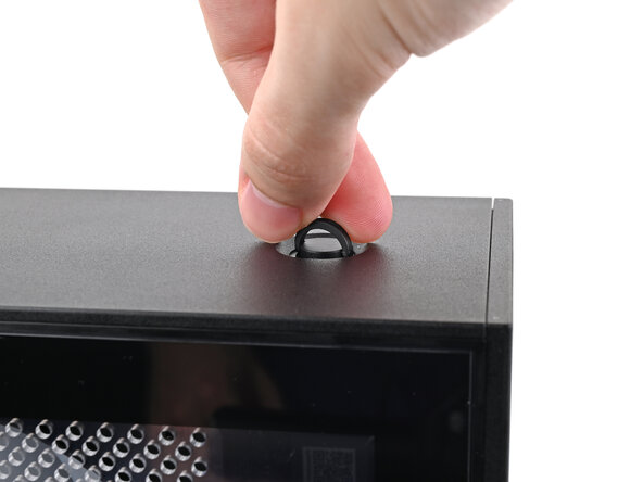
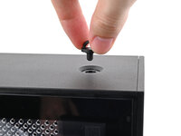
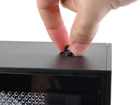
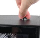
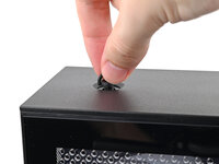
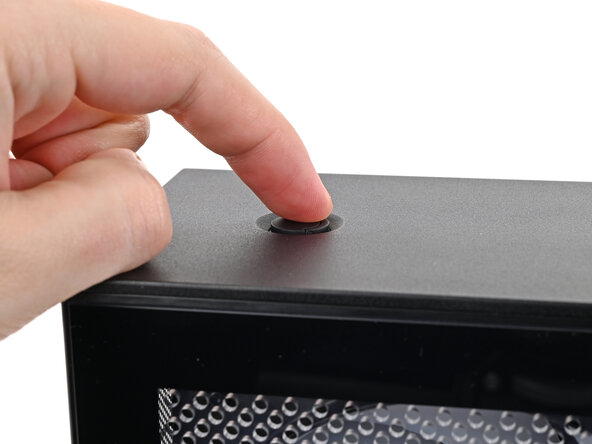
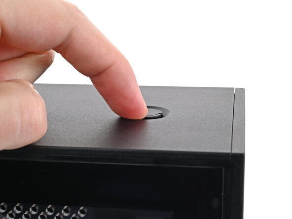
Use your finger to lift up the two D-rings on the Top Panel screws.
-
-
-
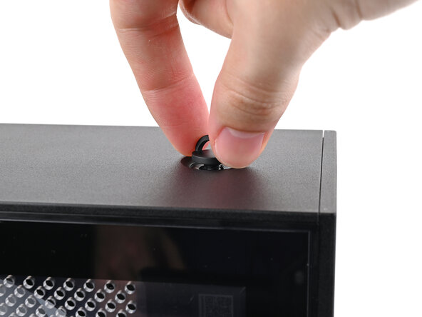
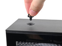
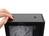
Use your fingers to twist the screw counter-clockwise and loosen it.
-
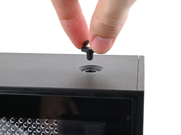
Remove the Top Panel screw.
-
-
-
Repeat the same procedure for the other Top Panel screw.
-
-
-
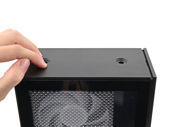
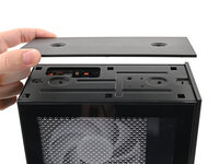
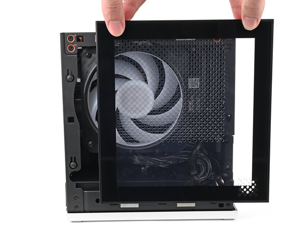
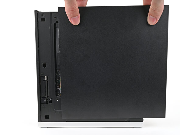
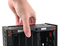
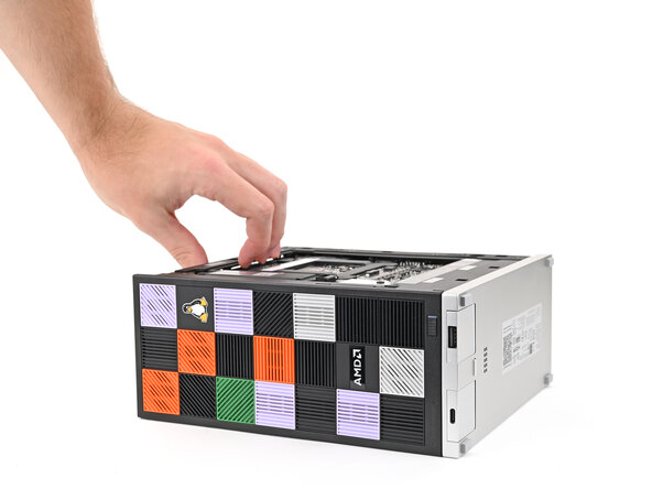
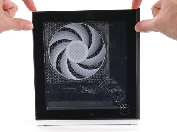
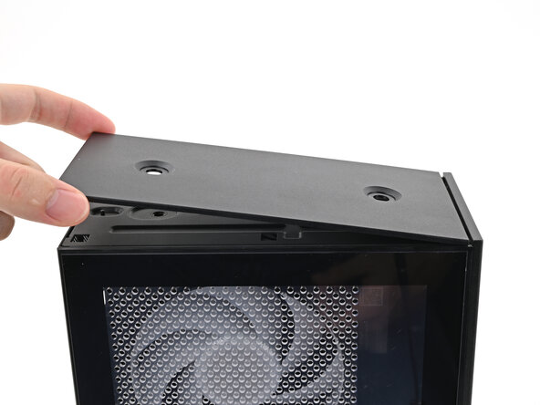
Slide the Top Panel towards the rear of the computer to release the clips securing it to the chassis.
-
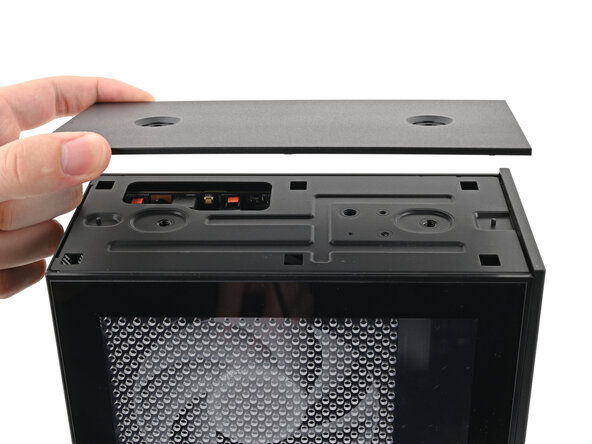
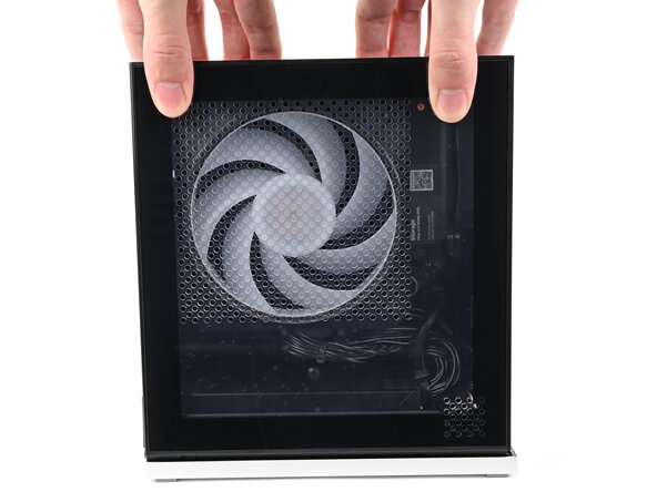
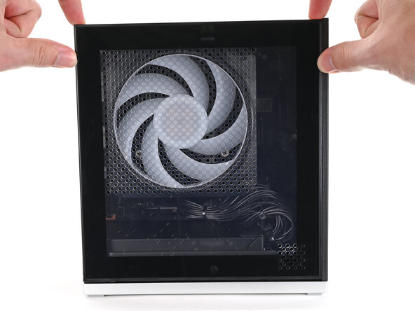
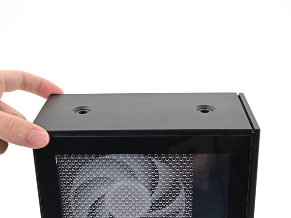
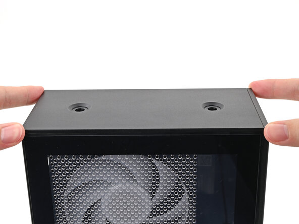
Lift the Top Panel off the chassis and remove it.
-
-
-
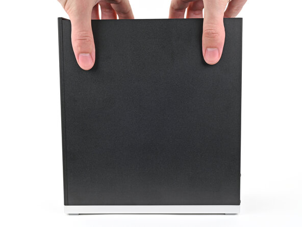
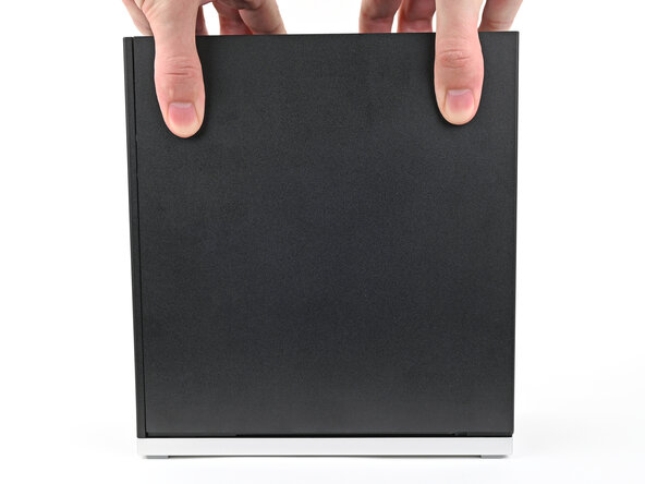
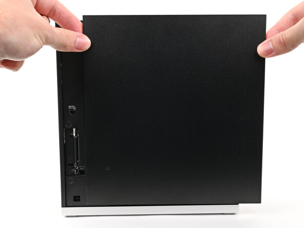
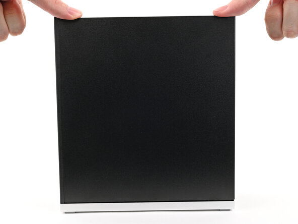
Use your fingers to grip the top of the Left Panel and slide it upward to release its clips.
-
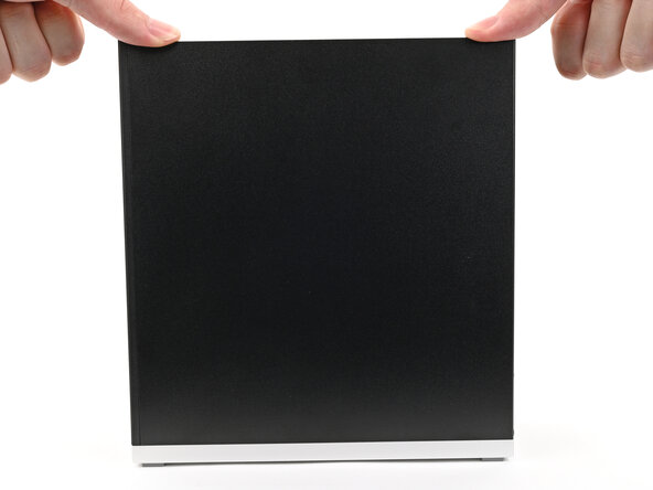
Remove the Left Panel.
-
-
-
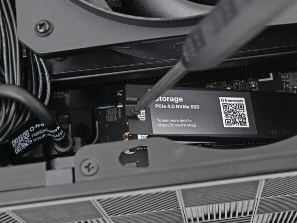
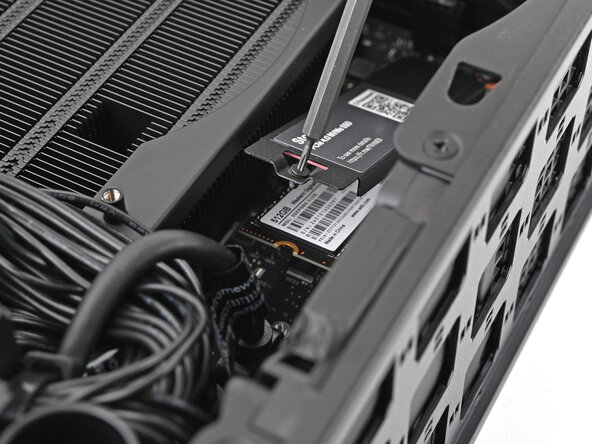
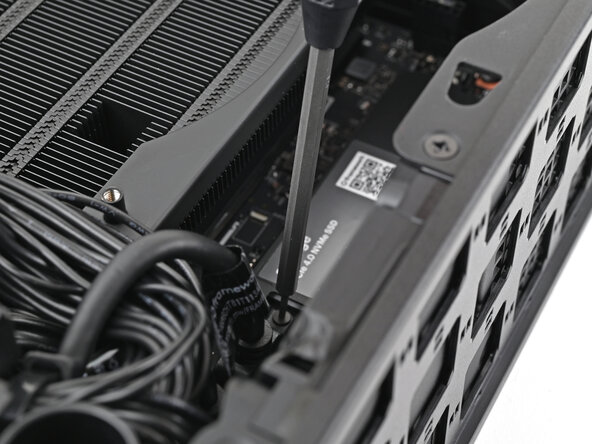
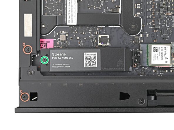
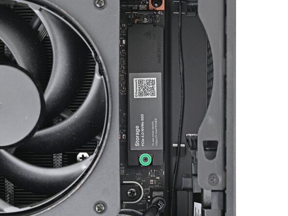
Use your Framework Desktop Screwdriver to loosen the captive T5 Torx screw securing the SSD.
-
-
-
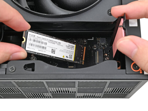
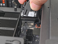
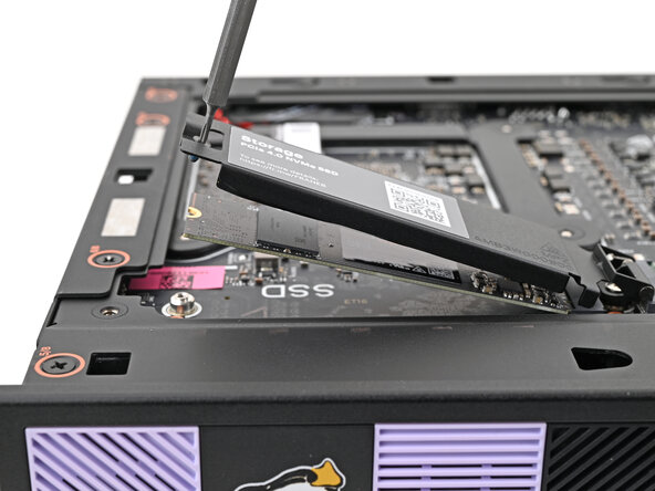
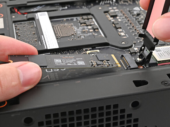
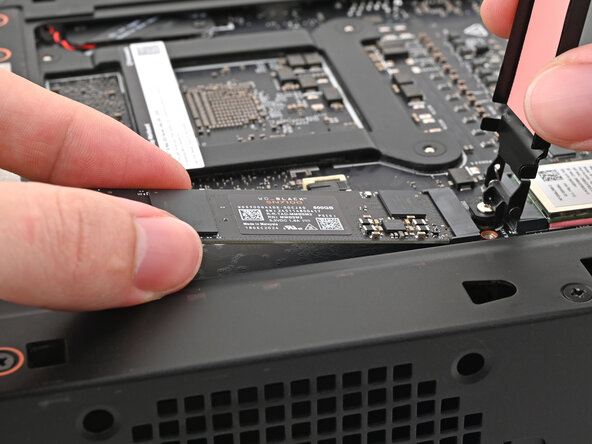
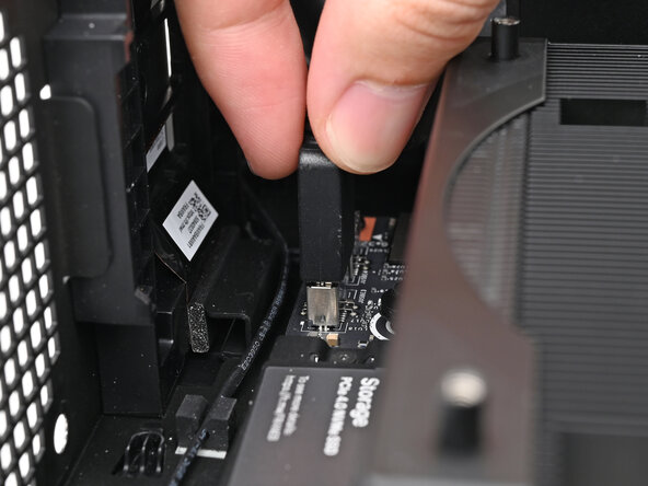
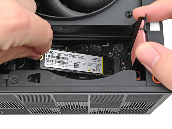
While holding the heat spreader upright, grab the SSD by its edges and pull it out of its socket.
-
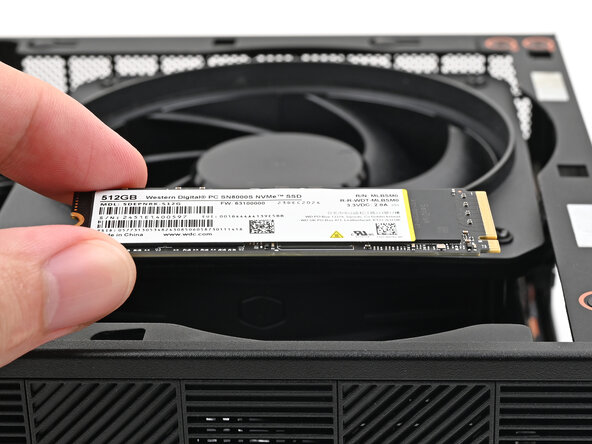
Remove the SSD.
-
-
-
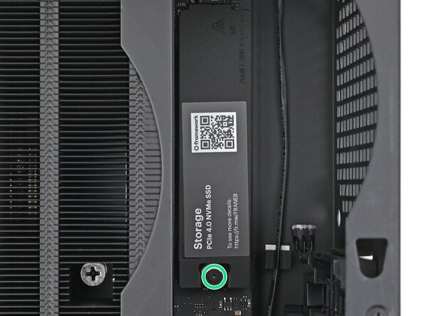
Insert your Framework Desktop Screwdriver into the captive screw on the primary storage heat spreader and press it flat to the Mainboard.
-
Tighten the captive T5 Torx screw securing the heat spreader.
-
-
-
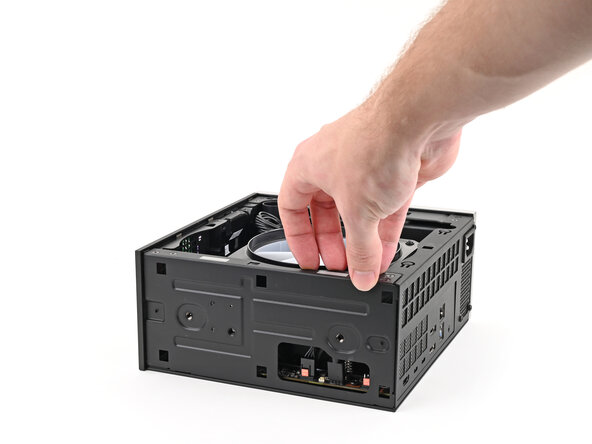
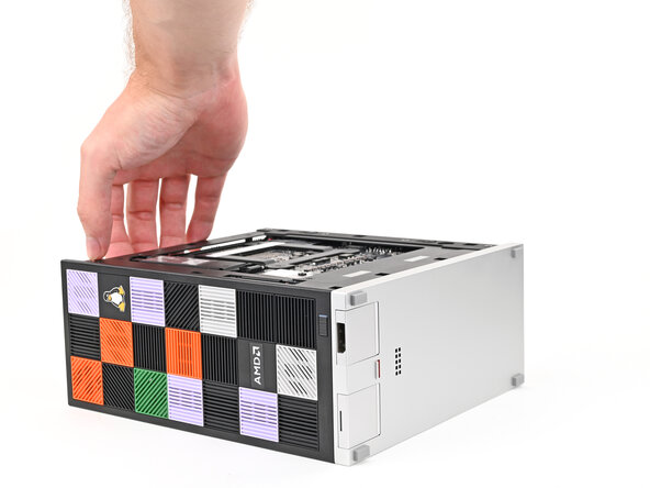
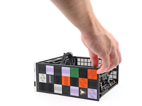
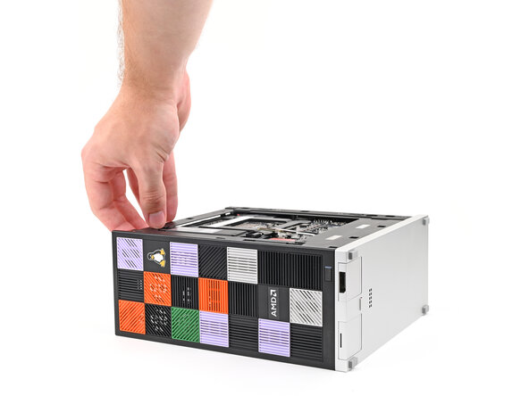
Lay down the Desktop on its side so the fan is facing upward.
-
-
-
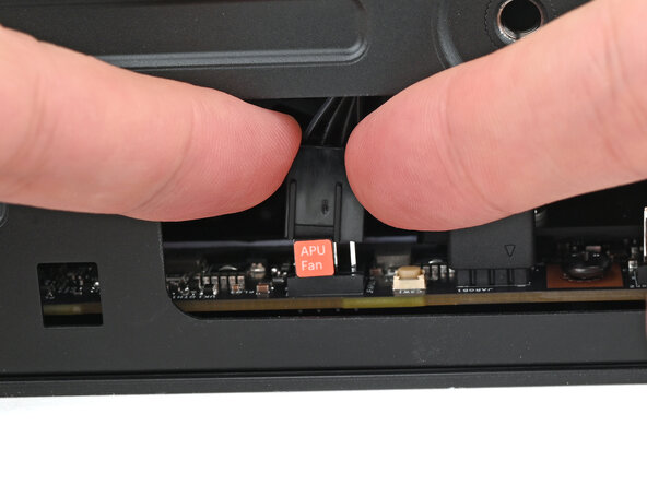
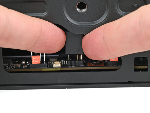
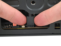
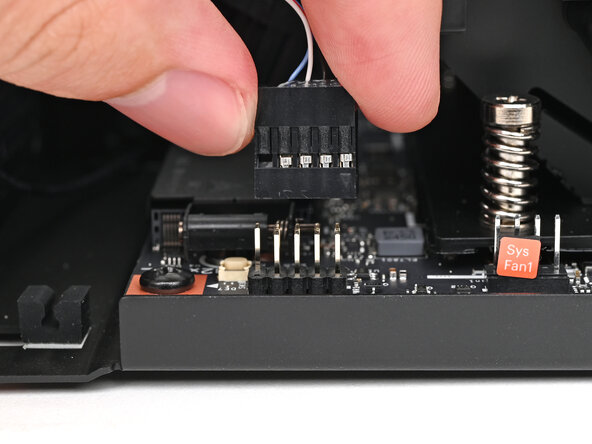
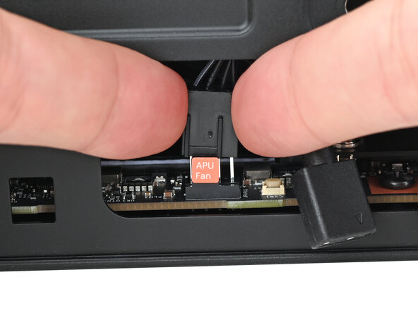
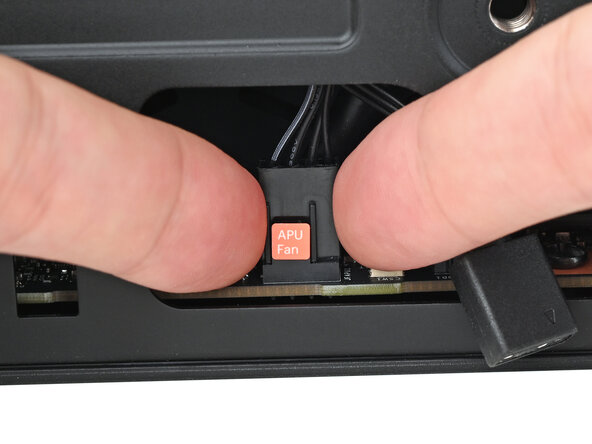
Use your fingers to lift the APU fan cable connector off its four‑pronged socket on the Mainboard.
-
-
-
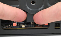
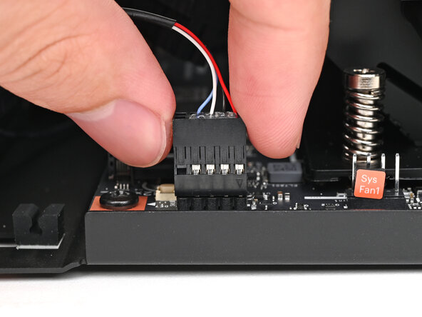
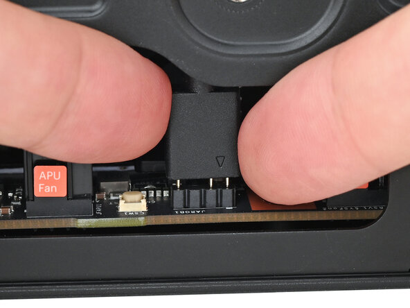
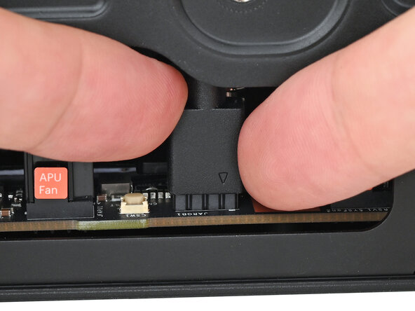
Use your fingers to lift the fan RGB cable connector off its three‑pronged socket on the Mainboard.
-
-
-
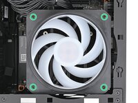
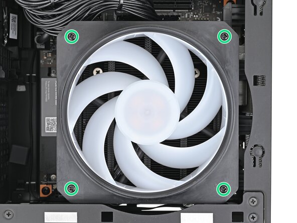
Use your Framework Desktop Screwdriver to remove the four 27.3 mm‑long Phillips screws securing the CPU fan and fan duct.
-
-
-
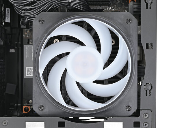
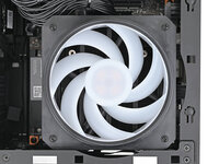
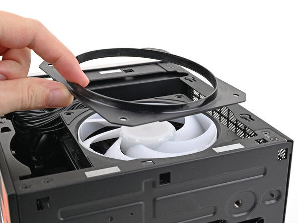
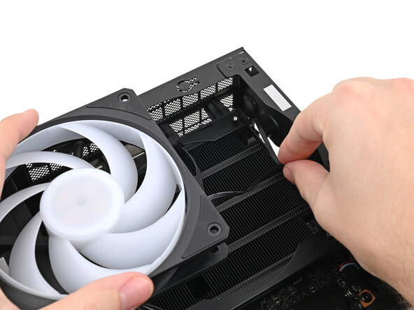
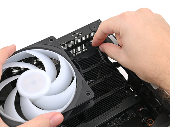
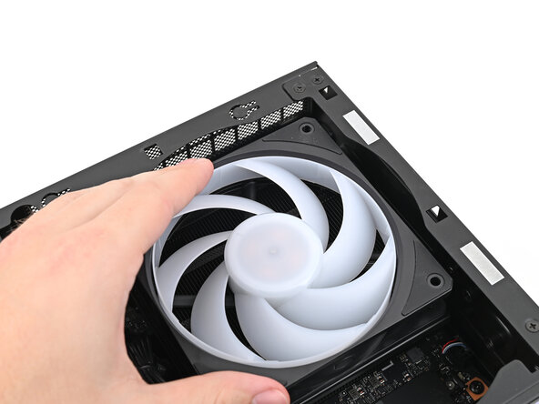
Lift the fan duct off the fan and remove it.
-
-
-
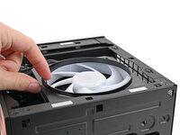
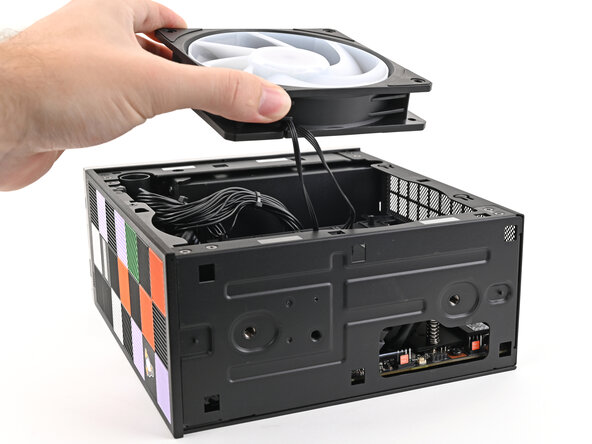
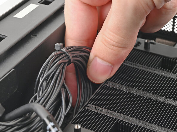
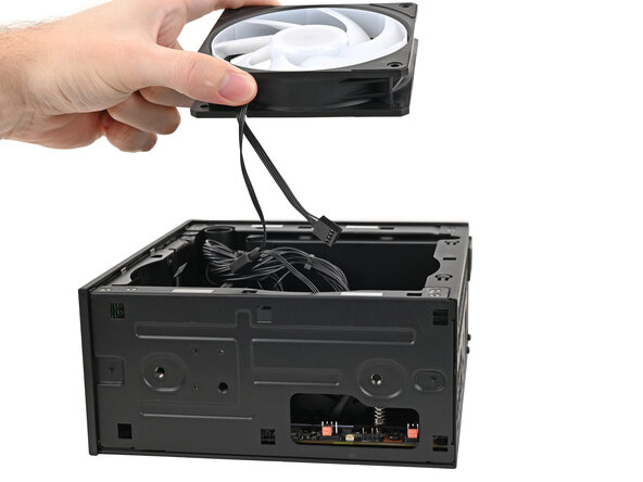
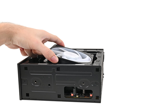
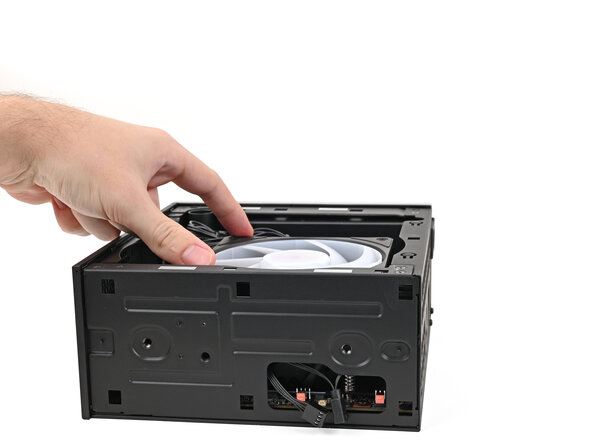
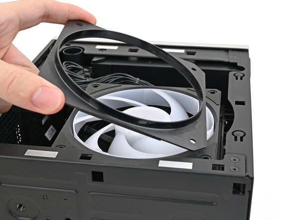
Lift the fan out of the chassis, making sure the cables thread through the side of the heatsink.
-
-
-
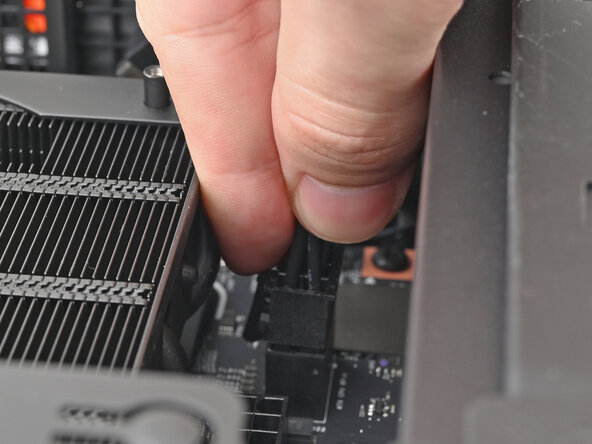
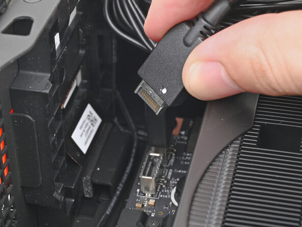
Pull the top Expansion Card connector straight out of its socket in the Mainboard to disconnect it.
-
-
-
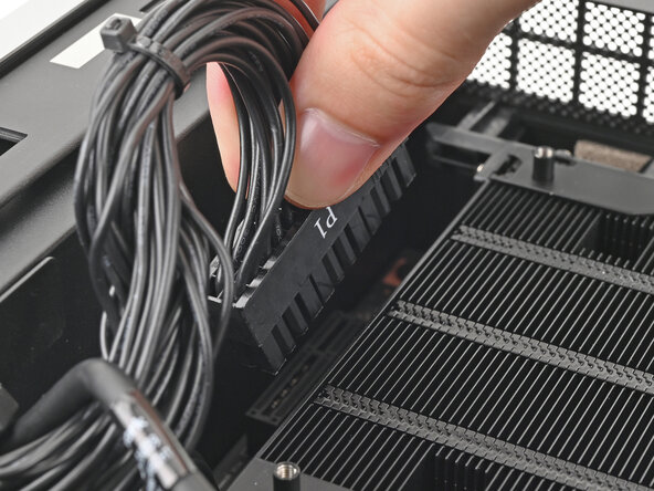
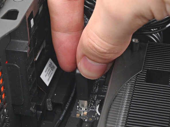
While squeezing the clip on the main power cable, pull it straight up and out of its socket to disconnect it.
-
-
-
While squeezing the clip on the CPU power cable, pull it straight up and out of its socket to disconnect it.
-
-
-
Pull the bottom Expansion Card connector straight out of its socket in the Mainboard to disconnect it.
-
-
-
Lift the Desktop so it stands upright on your work surface.
-
-
-
Use your fingers to grip the top of the Right Panel and slide it upward to release its clips.
-
Remove the Right Panel.
-
-
-
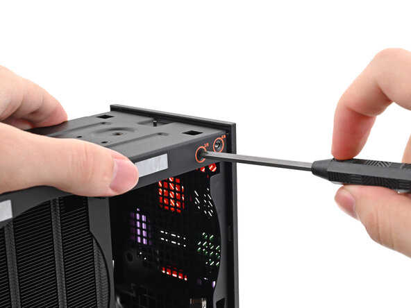
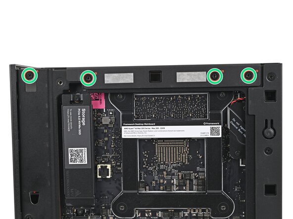
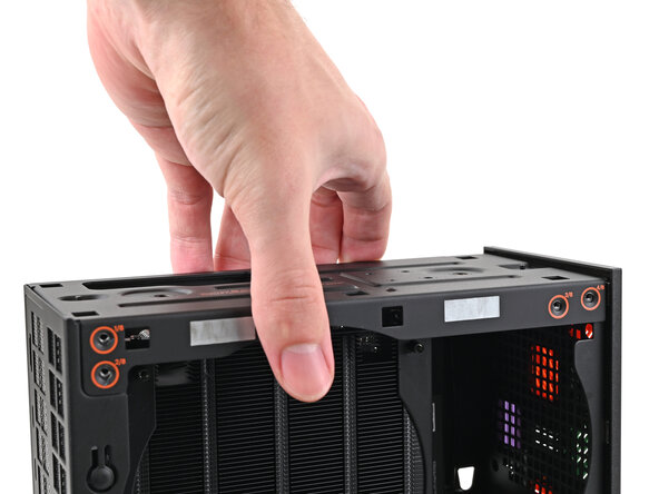
While holding the Desktop steady, use your Framework Desktop Screwdriver to remove the eight 4.0 mm‑long Phillips screws securing the top plate.
-
-
-
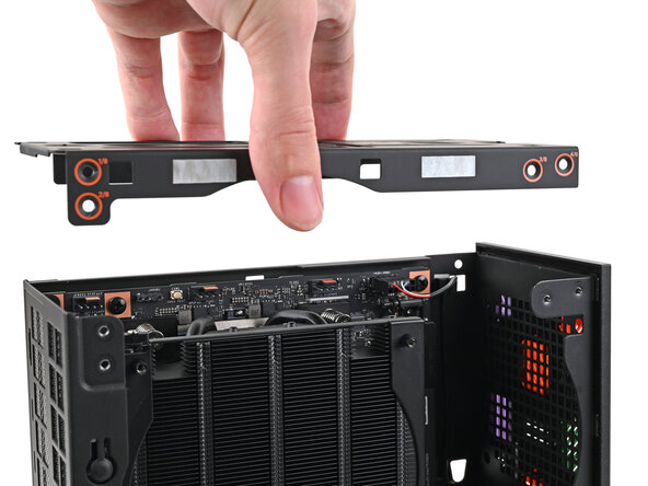
Lift the top plate off the Desktop and remove it.
-
-
-
-
Lay the left side of the Desktop on your work surface so the underside of the Mainboard is facing upward.
-
-
-
Use your Framework Desktop Screwdriver to loosen the captive T5 Torx screw securing the SSD.
-
-
-
While holding the heat spreader upright, grab the SSD by its edges and pull it out of its socket.
-
Remove the SSD.
-
-
-
Use your Framework Desktop Screwdriver to tighten the captive T5 Torx screw securing the heat spreader.
-
-
-
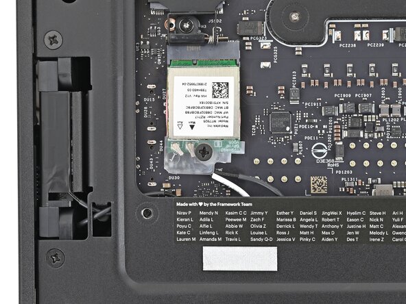
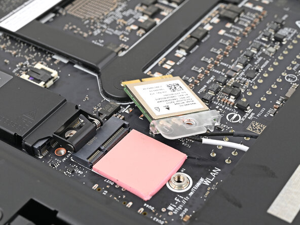
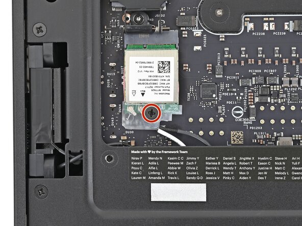
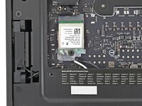
Use your Framework Desktop Screwdriver to remove the 7.0 mm‑long Phillips screw securing the Wi-Fi module.
-
-
-
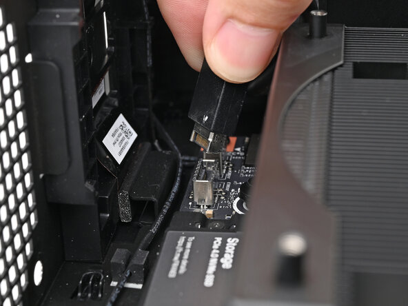
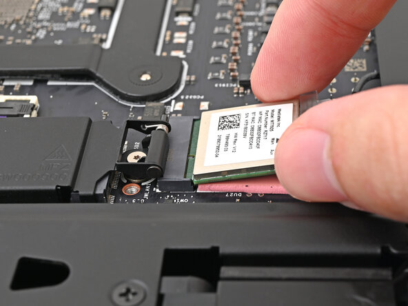
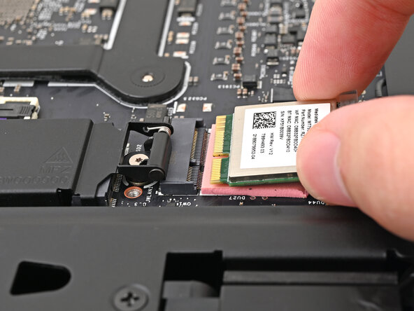
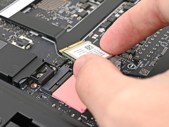
Grip the Wi-Fi module by its edges and pull it straight out of its socket.
-
-
-
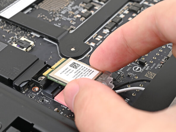
Move the Wi-Fi module towards the center of the Mainboard to keep it out of the way.
-
-
-
Rotate the Desktop onto its right side so the Mainboard is facing upward.
-
-
-
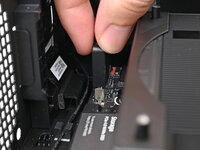
Use your fingers to lift the power button cable connector off its nine‑pronged socket on the Mainboard.
-
-
-
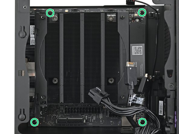
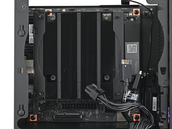
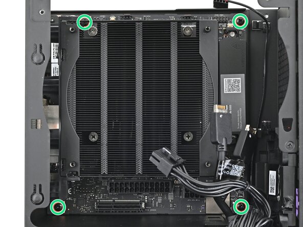
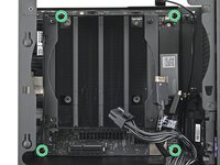
Use your Framework Desktop Screwdriver to remove the four 8.2 mm‑long Phillips screws securing the Mainboard.
-
-
-
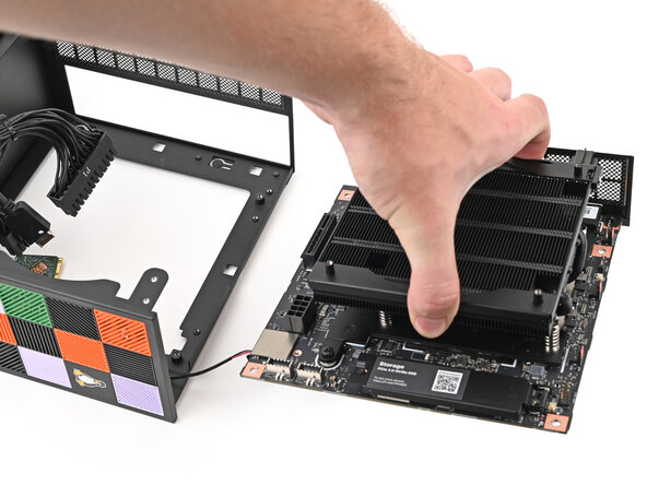
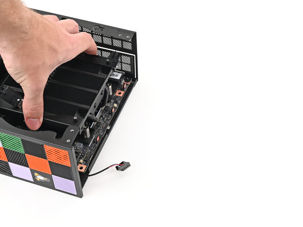
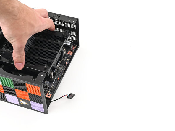
Grab the Mainboard by its heatsink and pull it towards the front of the Desktop to slide it out of the rear port cutout.
-
Slide the Mainboard towards the top of the Desktop to remove it from the chassis.
-
-
-
Congratulations on completing disassembly! The remaining steps will show how to reassemble your Framework Desktop.
-
-
-
Grab the Mainboard by its heatsink and slide it into the chassis.
-
Align the rear ports with its cutout and the screw posts with the screw holes on the Mainboard.
-
Make sure no cables are trapped underneath the Mainboard before continuing.
-
-
-
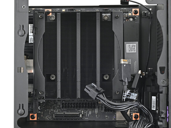
Use your Framework Desktop Screwdriver to install the four 8.2 mm‑long Phillips screws securing the Mainboard.
-
-
-
Slide the power button cable over the nine-pronged connector on the Mainboard.
-
-
-
Rotate the Desktop onto its left side so the underside of the Mainboard is facing upward.
-
-
-
Align the Wi-Fi module's gold contacts and notch with the socket on the Mainboard.
-
Insert the Wi-Fi module into the socket at a shallow angle. The gold contacts should mostly be covered by the socket.
-
-
-
Use your Framework Desktop Screwdriver to install the 7.0 mm‑long Phillips screw securing the Wi-Fi module.
-
-
-
Use your Framework Desktop Screwdriver to loosen the captive T5 Torx screw securing the heat spreader.
-
-
-
While holding the SSD heat spreader upright, align the SSD's gold contacts with its socket.
-
Insert the SSD into the socket at a shallow angle. The gold contacts should mostly be covered by the socket.
-
Lay the heat spreader back onto the SSD.
-
-
-
Use your Framework Desktop Screwdriver to tighten the captive T5 Torx screw securing the SSD.
-
-
-
Rotate the Desktop so it sits upright on your work surface.
-
-
-
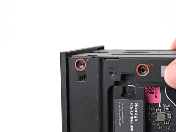
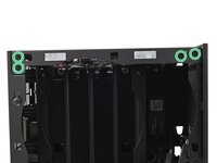
Place the top plate on top of the Desktop, making sure it slots into the chassis so the orange circles are visible.
-
-
-
Make sure the matching screw hole on the top plate labeled "5/8" is slotted on the inside of the Chassis so that the orange circle is visible.
-
-
-
While holding the Desktop steady, use your Framework Desktop Screwdriver to install the eight 4.0 mm‑long Phillips screws securing the top plate.
-
-
-
Slide the Right Panel onto the right edge of the chassis, from top to bottom, and press it flat to ensure its clips are slotted into place.
-
Push the Right Panel towards the base of the computer to engage the clips.
-
-
-
Lay the right side of the Desktop on your work surface so the Mainboard is facing upward.
-
-
-
Slide the bottom Expansion Card cable into its socket on the Mainboard.
-
-
-
Orient the CPU power supply cable so its clip is facing the heatsink.
-
Slide the cable into its socket on the Mainboard until you feel it click into place.
-
-
-
Orient the main power supply cable so its clip is facing away from the heatsink.
-
Slide the cable into its socket on the Mainboard until you feel it click into place.
-
-
-
Slide the top Expansion Card cable into its socket on the Mainboard.
-
-
-
Orient the fan so its label is facing downward and the cable(s) is pointing towards the top of the computer.
-
Lay the fan on top of the heatsink, making sure the cables are routed so they poke out of the hole on the top of the computer.
-
-
-
If the cables aren't routed properly, lift the fan up slightly and use your fingers to reposition the cables over the side of the heatsink.
-
-
-
Lay the fan duct on top of the fan with the lip facing upward.
-
Align the screw holes on the fan duct with the ones on the fan.
-
-
-
Use your Framework Desktop Screwdriver to install the four 27.3 mm‑long screws securing the fan and fan duct.
-
-
-
Orient the main fan cable so its two vertical lines are facing you.
-
Slide the main fan cable over the four-pronged connector labeled "APU Fan," making sure the orange label slots between the vertical lines.
-
-
-
Orient the RGB cable so the arrow is on the right side of the connector.
-
Use your fingers to slide the RGB cable over the three pronged connector located to the right of the "APU Fan" connector.
-
-
-
Use your Framework Desktop Screwdriver to loosen the captive T5 Torx screw securing the SSD.
-
-
-
While holding the heat spreader upright, align the SSD's gold contacts with its socket.
-
Insert the SSD into the socket at a shallow angle. The gold contacts should mostly be covered by the socket.
-
-
-
Insert your Framework Desktop Screwdriver into the captive screw on the primary storage heat spreader and press it flat to the Mainboard.
-
Tighten the screw securing the SSD.
-
-
-
Slide the Left Panel onto the left edge of the chassis and press it flat to ensure its clips are slotted into place.
-
Push the Left Panel towards the base of the computer to close the gap and engage the clips.
-
-
-
Orient the Top Panel so its arrow is pointing towards the rear of the computer.
-
While holding the Top Panel at a slight downward angle, slide it across the top of the chassis (from rear to front) until you feel its clips catch.
-
Lay the Top Panel flat on the chassis to align the remaining clips.
-
-
-
While securing the computer with one hand, use the other hand to slide the Top Panel towards the front of the computer to close the gap and engage the clips.
-
-
-
Place the Handle over the Top Panel screw holes.
-
While holding the Handle in place, twist the screw threads on both sides clockwise until they're snug on the Top Panel.
-
-
-
Insert the top panel screw into its hole and twist clockwise until it feels snug.
-
-
-
Repeat the same procedure for the other top panel screw.
-
-
-
Use your finger to close the two D-rings on the top panel screws.
-


You finished fixing your Framework Desktop!
Take your e-waste to an R2 or e-Stewards certified recycler.
If you need help, contact Framework support.
crwdns2935221:0crwdne2935221:0
crwdns2935227:0crwdne2935227:0
