crwdns2915892:0crwdne2915892:0
This guide gives you a look at the major components of the Olympus Pen E-PL7 and provides complete disassembly instructions.
We highly suggest you use a magnetic project mat or an organization tray. This camera has many different types of screws and keeping them organized is key to proper reassembly.
crwdns2942213:0crwdne2942213:0
-
-
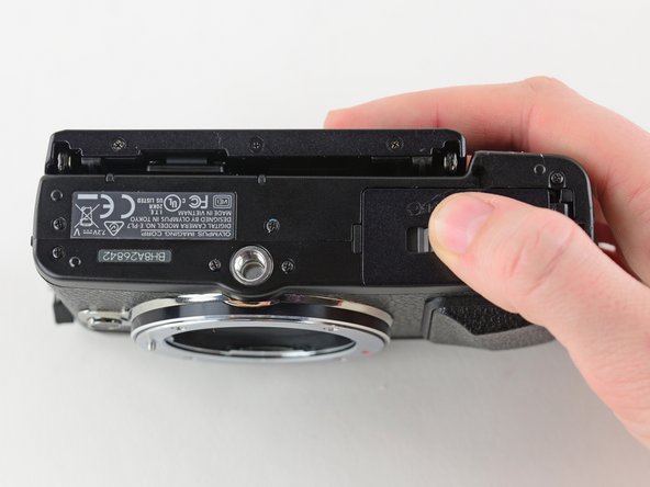
Turn the camera upside down.
-
Push the grey tab to the right to open the battery compartment.
-
Pull out the battery.
-
-
-
Use a Phillips #00 screwdriver to remove the six 2 mm screws on the bottom of the camera.
-
-
-
Remove the two 4 mm reverse threaded Phillips screws from the bottom of the camera.
-
-
-
Remove the two 4 mm Phillips screws under the HDMI port cover.
-
-
-
Use a Phillips #00 screwdriver to remove the 5 mm screw near the left hand grip.
-
-
-
Use a Phillips #00 screwdriver to remove the 5 mm screw near the right hand grip.
-
-
-
Flip open the LCD.
-
Use a Phillips #00 screwdriver to remove the 2 mm screw beneath the LCD assembly.
-
-
-
Use a Phillips #00 screwdriver to remove the four 6.3 mm screws from the lens mount.
-
-
crwdns2935267:0crwdne2935267:0Tweezers$4.99
-
Remove the lens mount with tweezers.
-
-
-
Use tweezers to remove the inner metal ring.
-
-
-
Use tweezers to remove the two springs lying beneath the inner metal ring.
-
-
-
Use a Phillips #00 screwdriver to remove the three 5 mm screws.
-
-
-
Remove the two 4 mm Phillips screws.
-
-
-
Press and hold the lens release button while using tweezers to remove the lens hook.
-
Use tweezers to remove the spring underneath the lens hook.
-
-
-
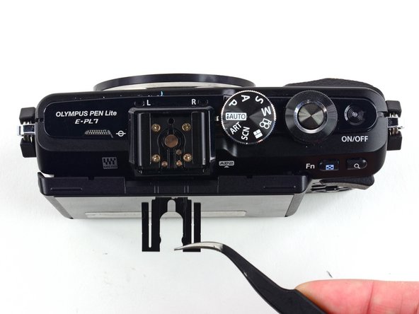
Use tweezers to remove the metal clip from the external flash mount.
-
-
-
Use a Phillips #00 screwdriver to remove the four 4 mm screws from the external flash port.
-
-
-
Remove the second external flash clip with tweezers.
-
-
-
Remove the external flash port casing to expose five more screws.
-
-
-
Use a Phillips #00 screwdriver to remove the two 6.4 mm screws.
-
Remove the 2 mm Phillips screw.
-
-
-
-
Remove the two 3.8 mm Phillips screws from the sides of the external flash connector.
-
-
-
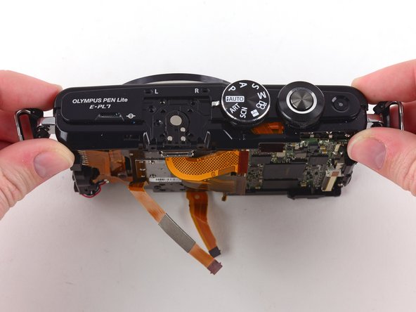
Gently pull the back case away from the camera.
-
-
-
To remove the ribbon holding the back case to the camera, use the pointed end of a spudger to flip back the top bar on top of the ZIF connector.
-
-
-
Use tweezers to pull the ribbon out of the connector.
-
Remove the back case.
-
-
-
Use a Phillips #00 screwdriver to remove the two 1.6 mm screws near the left hand grip.
-
-
-
Once the screws are removed, use two fingers to remove the metal clip.
-
-
-
Remove the 2.2 mm Phillips screw near the left hand grip, holding a second metal plate in place.
-
Remove the 1.8mm Phillips screw.
-
-
-
Once the screws are removed, use two fingers to remove the metal plate.
-
-
-
Remove the two 4.1 mm Phillips screws near the right hand grip.
-
-
-
Use a spudger to remove the three indicated ribbon cables from their ZIF connectors on the motherboard.
-
-
crwdns2935267:0crwdne2935267:0Tweezers$4.99
-
Use tweezers to remove the plastic cover from the two ZIF connectors in the upper left corner of the motherboard.
-
Disconnect both ribbon cables.
-
-
-
Desolder the large ribbon cable from the motherboard at the solder points on either side of its ZIF connector
-
Learn more about soldering with iFixit's Soldering Technique Guide.
-
-
-
Remove the 5.2 mm Phillips screw from the top of the right hand grip.
-
Remove the top plate.
-
-
-
Remove the sensor assembly from the front case.
-
-
-
Remove the two 4.3 mm screws from the front of the sensor assembly.
-
Remove the 6.8 mm screw.
-
-
-
Remove the four 1.9mm Phillips screws from the back of the sensor assembly.
-
Remove the 14.5mm Phillips screw.
-
Remove the 3.3mm Phillips screw.
-
-
-
Use a Phillips #00 screwdriver to remove the 1.7 mm screw securing the tripod mount to the ribbon cable.
-
Use tweezers to remove the small copper ring underneath the screw.
-
-
-
Desolder the red and black wires from the back upper right corner of the sensor assembly.
-
-
-
Pull the sensor frame away from the sensor assembly.
-
-
-
Remove the 4.4 mm Phillips screw securing the motherboard to the battery compartment.
-
Remove the 3.8 mm Phillips screw.
-
Remove the 3.7mm Phillips screw.
-
-
-
Remove the three 3.3 mm Phillips screws at the top of the motherboard.
-
-
-
Remove the 3.4 mm Phillips screw from the left side of the motherboard.
-
-
-
Remove the battery compartment by hand.
-
-
-
Use a Phillips #00 screwdriver to remove the three 2.3 mm screws from the base of the LCD screen.
-
-
-
Remove the two 2.2 mm Phillips screws located on the back of the LCD screen.
-
Use tweezers to remove the top bracket.
-
-
-
Use a Phillips #00 screwdriver to remove the four 1.4 mm screws from the back of the LCD screen.
-
Remove the LCD ribbon cable with a pair of tweezers.
-
-
-
Carefully lift the LCD screen up and away from the assembly.
-
-
-
Use tweezers to remove the plastic covering the LCD ribbon cable.
-
-
-
Use the flat end of a spudger to flip back the black bar on the ZIF connector.
-
-
-
Gently pull the ribbon cable out with tweezers.
-
-
-
Pull the ribbon cable through the hole in the LCD assembly.
-
-
-
Remove the four 2.4 mm Phillips screws from the inside of the back case.
-
-
-
Pull the LCD assembly away from the back case.
-
-
-
You have successfully disassembled the Olympus Pen E-PL7!
-


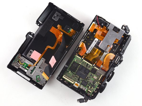


To reassemble your device, follow these instructions in reverse order.
To reassemble your device, follow these instructions in reverse order.
crwdns2935221:0crwdne2935221:0
crwdns2935229:07crwdne2935229:0

crwdns2947412:02crwdne2947412:0
Step 23. You should not be using pointed tweezers here. Or on any of the ribbon cables. They put pressure on the tip only only and could damage across tracks on the ribbon cable. Small long nose pliers with smooth jaws or even small pliers again with smooth jaws. Also for assembly the tweezers would be useless in many ribbon cable reinsertion positions. BTW they are nice tweezers but not for ribbon cables.
I have an EPL-7 in good condition, however, the on/off button has ceased working. It was a slow transition to not working. What could it be and should I spend the 200.00 dollars Olympus wants to service it? Thanks!