crwdns2915892:0crwdne2915892:0
If the motherboard in your Dell Latitude 3190 has failed or requires replacement due to damage or performance issues, this guide will walk you through the process step by step. A motherboard replacement can resolve critical problems like hardware failures, system crashes, or the inability to boot, restoring your device’s functionality.
Before starting, ensure the device is fully powered off, unplugged from the charger, and disconnected from any external peripherals. Work in a static-free environment, using an anti-static wrist strap if available, to protect sensitive components. This repair may be necessary if your Dell Latitude 3190 is experiencing system instability (e.g., frequent crashes or errors), has physical damage to the motherboard (e.g., burnt circuits or broken connectors), or requires an upgrade for compatibility with newer components.
The Dell Latitude 3190’s compact design may involve closely packed components, requiring extra care to avoid damaging cables, connectors, or nearby parts during disassembly and reassembly. Additionally, ensure compatibility between the replacement motherboard and your existing components. Follow this guide to complete your motherboard replacement safely and effectively. If you encounter challenges, seek professional assistance.
crwdns2942213:0crwdne2942213:0
-
-
Use a Phillips #0 screwdriver to remove the seven 7 mm screws securing the back case.
-
-
-
Using a plastic opening tool carefully separate the plastic base cover from the rest of the laptop.
-
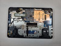
Lift the bottom cover from the laptop.
-
-
-
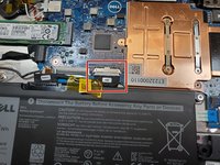
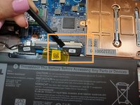
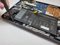
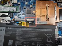
Disconnect the battery cable located on the top of the battery.
-
Use the spudger and disconnect the battery cable.
-
Pull the cable out of the way.
-
-
-
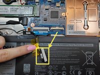
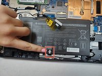
Use a Phillips #0 screwdriver to remove the three 3 mm screws from the battery.
-
-
-
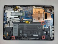
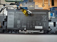
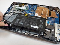
Pull the black battery tap upwards to remove the battery.
-
-
-
-
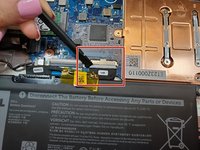
Use a spudger to disconnect the battery cable from the motherboard located at the top of the battery.
-
-
-
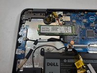
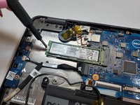
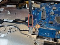
Locate the M.2 SSD after the battery is removed
-
Use the Phillips #0 screwdriver to remove the 3 mm screw from the SSD.
-
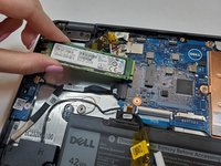
Pull the M.2 SSD from the board.
-
-
-
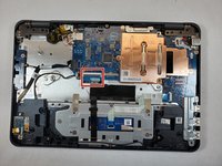
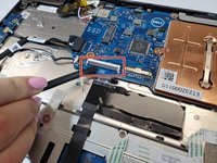
Remove the motherboard cable by pulling up on the black bar and carefully removing the blue ribbon cable.
-
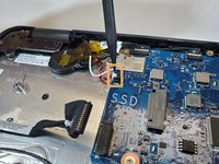
Disconnect the white speaker cable connector.
-
-
-
Using a spudger, disconnect the black power board and audio cable.
-
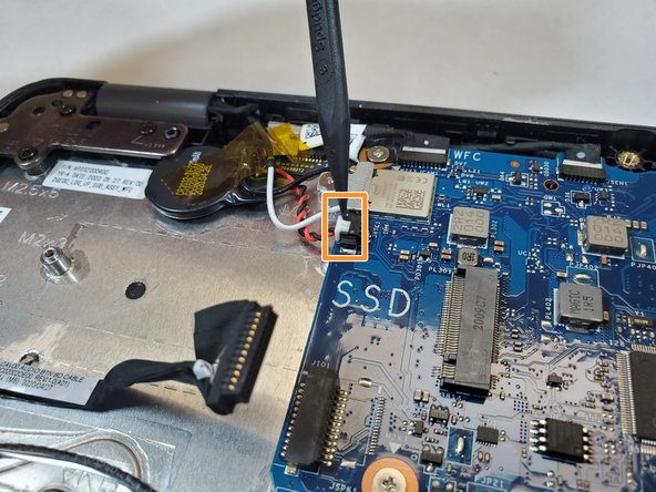
Disconnect the white coin cell battery cable.
-
-
-
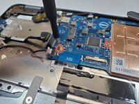
Use the Phillips #0 screwdriver to remove the 3 mm screw and lift the metal bracket that secures the WLAN card on the system board.
-
Disconnect the black and white WLAN cables.
-
-
-
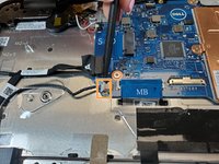
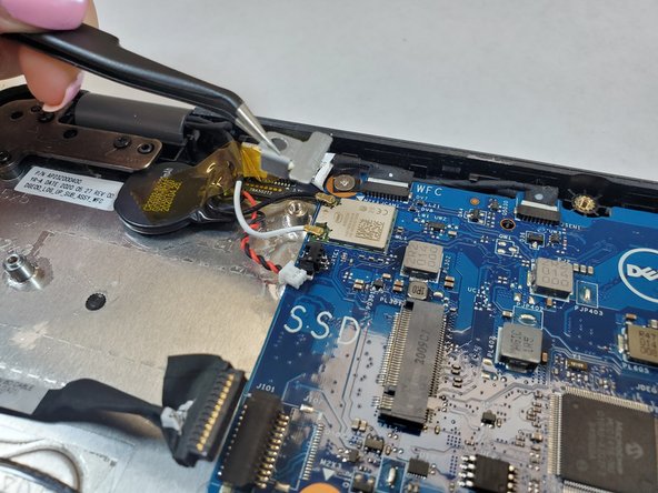
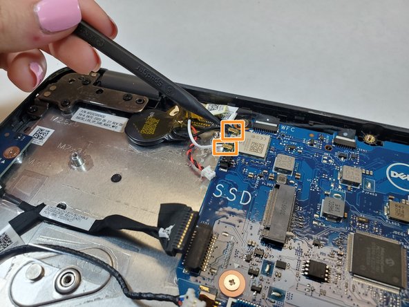
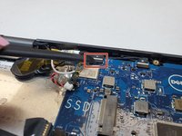
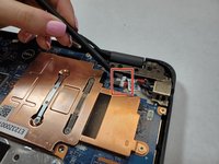
Remove the screw that secures the camera cable to the system board.
-
Disconnect camera cable.
-
Disconnect the black sensor cable.
-
-
-
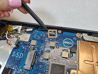
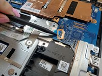
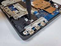
Use the Phillips #0 screwdriver to remove the two 3 mm screws from the metal bracket on the display cable.
-
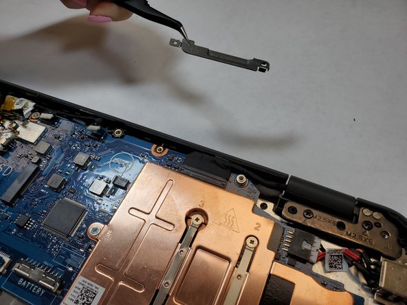
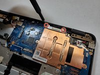
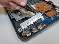
Lift the metal bracket that secures the display cable on the computer.
-
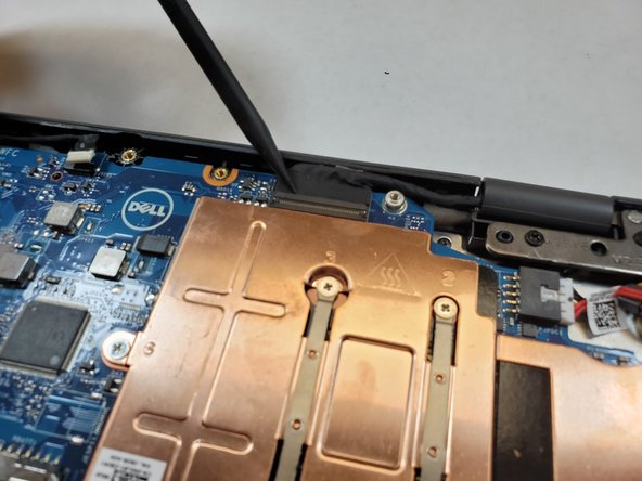
Disconnect the black display cable using a spudger or pull it out by hand.
-
-
-
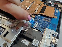
Disconnect the white power connector.
-
Use the spudger to lift up on black bar to release the trackpad ribbon cable.
-
Pull the blue tab release to the cable from the connector.
-
-
-
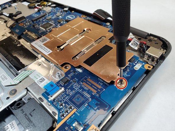
Use a Phillips #0 tp remove the two 3 mm screws on the metal bracket that secures the board.
-
Remove the metal bracket.
-
-
-
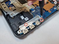
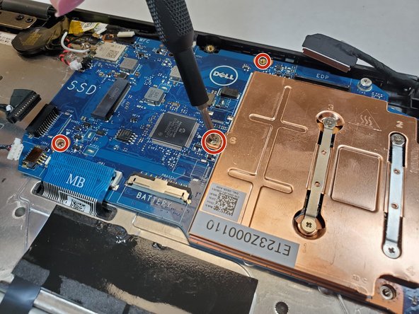
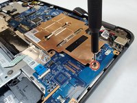
Use the Phillips #0 screwdriver to remove the five 3 mm screws that secure the motherboard.
-
-
-
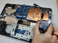
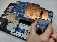
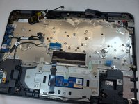
Carefully lift the motherboard up to remove it from the computer.
-


To reassemble your device, follow these instructions in reverse order. Take your e-waste to an R2 or e-Stewards certified recycler.
To reassemble your device, follow these instructions in reverse order. Take your e-waste to an R2 or e-Stewards certified recycler.
crwdns2935221:0crwdne2935221:0
crwdns2935227:0crwdne2935227:0

crwdns2915084:0crwdne2915084:0

Gateway, Team 1-5, Saknee Fall 2021 crwdns2935289:0Gateway, Team 1-5, Saknee Fall 2021crwdne2935289:0
GCC-SAKNEE-F21S1G5
crwdns2931471:03crwdne2931471:0
crwdns2935297:09crwdne2935297:0