crwdns2942213:0crwdne2942213:0
-
-
Close the display and turn over the computer to see the battery locking tabs.
-
-
-
Pull both of the locking tabs outwards until they both click to release the battery.
-
Pull the battery out by lifting it from the top and sliding it forward.
-
-
-
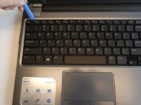
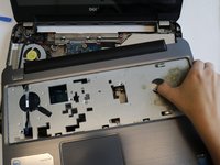
Turn the laptop over so that the keyboard is facing up.
-
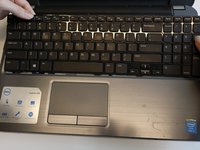
Use an opening tool to pry the keyboard from the base of the laptop.
-
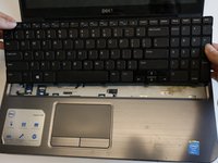
Once the top of the keyboard is released, slide the keyboard upwards.
-
-
-
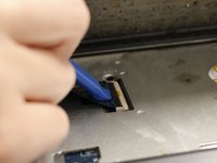
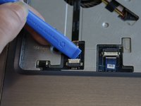
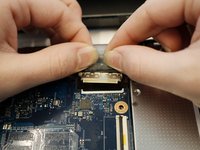
Use an opening tool to remove the keyboard ribbon from the latch by lifting the tab on top.
-
Once lifted, disconnect the ribbon and replace with a new keyboard.
-
-
-
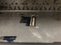
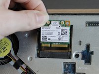
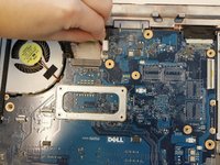
Once the keyboard is removed, the Wi-Fi module will be accessible.
-
-
-
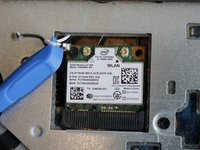
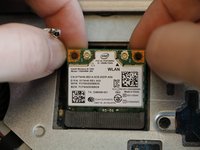
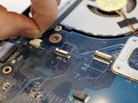
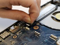
Use the opening tool to lift both antenna cables upward from the Wi-Fi module.
-
-
-
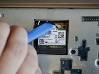
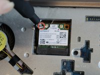
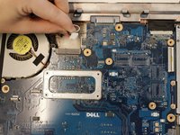
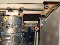
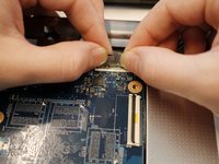
Remove the 3mm Phillips #000 screw securing the Wi-Fi module.
-
Lift the Wi-Fi module up and out of the laptop.
-
-
-
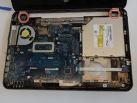
Remove the screws that secure the hard-drive assembly to the computer base.
-
-
-
-
Slide the hard-drive assembly forward to disconnect the hard-drive assembly from the system board.
-
-
-
Using the pull-tab, lift the hard-drive assembly out of the computer base.
-
-
-
Remove the screws that secure the hard-drive bracket to the hard drive.
-
-
-
Lift the hard-drive bracket off the hard drive.
-
-
-
Align the screw holes on the hard-drive bracket with the screw holes on the NEW hard drive.
-
-
-
Replace the screws that secure the hard-drive bracket to the hard drive.
-
-
-
Slide and place the hard-drive assembly in the hard-drive bay.
-
-
-
Slide the hard-drive assembly backward to connect the hard-drive assembly to the system board.
-
-
-
Replace the screws that secure the hard-drive assembly to the computer base.
-
-
-
Remove thirteen 5mm Phillips #000 screws from the back cover of the laptop.
-
-
-
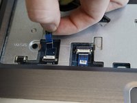
Use the opening tool to unplug the palm rest cables and slide the cables out.
-
-
-
Remove seven 5mm Phillips #000 screws from the midframe.
-
-
-
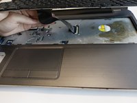
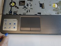
Use the opening tool to lift the edges of the palm rest. Once all of the sides are lifted, pull the palm rest off.
-
-
-
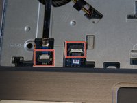
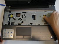
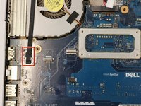
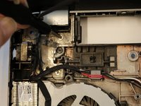
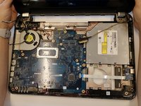
Unplug the DC jack to the right of the fan.
-
-
-
Unplug the display cable below the fan by pulling the cable straight back.
-
-
-
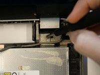
Unplug the display cable located near the right display hinge by lifting the tape and pulling back.
-
-
-
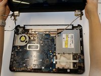
Remove the two 5mm Phillips #000 screws from the left and right hinges.
-
-
-
Remove the display assembly by lifting the display from the hinges.
-


To reassemble your device, follow these instructions in reverse order.
crwdns2935221:0crwdne2935221:0
crwdns2935227:0crwdne2935227:0


crwdns2947410:01crwdne2947410:0
Thanks for showing it all. Do you know where are the touchscreen and camera cables? I suspect mine are loose because the screen does not respond to touches anymore and lately the camera has stoped working albeit still being recognized. Thanks and best regards, Fábio.