crwdns2915892:0crwdne2915892:0
Wenn sich die Maschine nicht mehr einschalten lässt, kann die Leistungsplatine defekt sein. Meistens sind die Bauteile des Schaltnetzteils durchgebrannt. Die Teile sind nicht teuer, ein Reparaturversuch lohnt sich. Du musst allerdings ziemlich gut löten/entlöten können, wir haben dazu eine Anleitung.
Die Bauteile sind recht leicht im Elektronikhandel zu erhalten, insbesondere benötigst du eine Widerstand 47 Ohm, 3W, eine Induktivität 1mH und einen IC LNK364GN
crwdns2942213:0crwdne2942213:0
-
-
Entferne alle Anbauteile wie Wassertank, Tresterschublade, Brühgruppe.
-
Drehe die Maschine mit der Rückseite zu dir.
-
Entferne fünf Torx T20 Security Schrauben.
-
-
-
Hebe die Rückseite heraus.
-
Folgende Bauteile sind gleich sichtbar:
-
Mahlwerk
-
Pumpe
-
Flowmeter
Sehr gute Anleitung. Die Security Schrauben der Rückwand können auch durch normale Kreuzschlitzschrauben ersetzt werden. Natürlich mit gleichen Abmessungen. Es erleichtert bei späteren Reparatur Arbeiten die Werkzeuge Auswahl , da überall Kreuzschlitzschrauben verbaut sind.
-
-
-
Schiebe auch die Abdeckung - falls noch nicht geschehen - auf der Wassertankseite nach hinten und entferne sie.
-
-
-
-
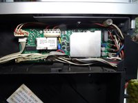
Unter der Abdeckung liegt die Leistungsplatine. Sie ist mit vier Schrauben in den Ecken befestigt und mit einer Menge Kabel angeschlossen.
-
Schiebe die Kabel ein wenig zur Seite und drehe die vier Kreuzschlitzschrauben in den Ecken heraus.
-
-
-
Die Kabel haben viele verschiedene Verbinder und können fast nicht verwechselt werden. Notiere dir insbesondere, wo die Flachstecker angeschlossen sind.
-
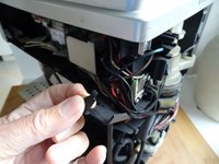
Die Flachstecker lassen sich leichter lösen, wenn du die Abdeckung in der Ecke des Gerätes zur Seite hebst.
-
Hole die Platine ein paar Zentimeter heraus.
-
Löse behutsam alle Verbindungen. Einige sind mit Rasten gesichert, die du erst wegdrücken musst.
-
-
-
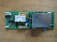
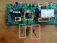
Hier ist die Leistungsplatine. Das Aluminiumkühlblech ist nur mit drei Laschen auf der Rückseite der Platine befestigt. Stelle die drei Laschen mit einer Zange gerade und hebe das Kühlblech heraus. Achte darauf, dass es an einem Triac festgeklemmt ist.
-
-
-
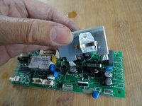
Hier die entscheidenden Bauteile:
-
R55: Widerstand, 47 Ohm, 3 W
-
L1: Induktivität 1mH
-
U1: Switcher IC LNK364GN
-
-
-
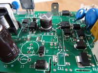
Entlöte zunächst diese drei Bauteile. Benutze eine Entlötsaugpumpe und/oder Entlötlitze. Das Auslöten des ICs ist knifflig, es handelt sich um eine SMD-Version. Es geht leichter, wenn du den Kondensator C3 vorher auch noch auslötest, eventuell kannst du die Pins des ICs auch vorsichtig abschneiden.
-
Überprüfen der Bauteile:
-
Bei dieser Platine war die Induktivität L1 deutlich erkennbar defekt, sie war schwarz , gelbe Perlen waren ausgeschwitzt, der Widerstand viel zu hoch, er sollte im Bereich um 3 Ohm liegen.
-
Der 47 Ohm Widerstand R55 war unendlich - so kann nichts mehr funktionieren.
-
Der IC LNK364 war wohl der Auslöser des Defekts, zwischen den beiden Pins mit der großen Lücke soll der Widerstand einige MegOhm sein, er war nur wenige Ohm.
-
Überprüfe zur Sicherheit auch noch die Diode D1 (in eingebautem Zustand) , sie soll nur in einer Richtung leiten. Falls defekt, ersetze sie durch eine 1N4005. (Kathode, also minus in Richtung L1)
-
Löte alles wieder ein und trinke erst mal einen Kaffee... es könnten ja auch noch andere Bauteile defekt sein...
-


Arbeite die Schritte in umgekehrter Reihenfolge ab, um dein Gerät wieder zusammenzubauen.
Arbeite die Schritte in umgekehrter Reihenfolge ab, um dein Gerät wieder zusammenzubauen.
crwdns2935221:0crwdne2935221:0
crwdns2935229:03crwdne2935229:0
crwdns2947412:021crwdne2947412:0
Hallo die Anleitung, passt im wesentlich auch zur ECAM 23 450S - die Platine sieht etwas anders aus - man muss kein Kühlblech demontieren, die Bauteile tragen die gleichen Nummern / Bezeichnungen. Nach dem Wechsel läuft unsere Minna wieder. Danke - auf die nächsten 12 Jahre.
Freut mich, Grüße.
VauWeh -
Hallo,
ESAM 3600, die Platine ist auch anders die baustein Bezeichnung ist gleich.
Reparatur hat dank Anleitung bestens geklappt.
Danke
LG Dieter
Interessante Info, danke. Freut mich, dass es geklappt hat.
VauWeh -
Thank you for sharing! Had the same problem with mine, thanks to your guide I could repair the board and the machine works well as before. Nice!
Robert
I'm glad to hear that. Another machine saved. Repair is war on entropy!
VauWeh -
Below the two white relays there's a component on Q1. Can you or anyone else help me find out what that is? Mine is blown and unidentifiable, I assume Q2 is probably the same but Q2 is unpopulated on my board so I have nothing to compare with.
Thank you for the reply. Yes what I refered to is the two white relays, that usually have a sticker with the board part number and software version on top of them.
In the meantime I may or may not have found some useful information for me and anyone else needing to diagnose and repair these boards. There are a some variance between machine models, but that appears to mostly be software and which components are populated, not so much different components.
In my case, it seems Q1 and Q2 is an SOT-23 packaged P-channel FET. Component CHT2301PT (this is discontinued) or TSM2301. Alternatively, PNP Resistor Equipped Transistor: PDTA143ET.
I'm pretty sure it's a not allowed to share scematics or links to such material on Ifixit. But lets instead imagine for a moment; some hypothetical Oogle might reference something called "delonghi_ecam_21.116_21.117_22.110_parts_schema_pcb" as a source of... useful information :)
@prollie do you mean the document on the bottom of this page DeLonghi ECAM Series Nice find. It'll be a lot easier to keep it here than to have to go through a search engine and all that stuff. This way people can focus on helping you instead of hunting for it :-) You got the iFixit Guru @vauweh working on it so you know it'll be resolved :-) Repair is War on Entropy!
@prollie @oldturkey03 Well - this fault ist unknown to me and I appreciate the link! I hope that replacing the parts is the right solution. Otherwise there ist another possibility (for european users): When I had issues like yours, they did the job.
I have same problem with my coffee machine. I have made quick lookup with schematic and multimeter and everything looks fine expect U1 - LNK364GN. it seems strange to me that only U1 would be at fault and it would be enough to replace only U1. Why is it destroyed? Any suggestions?
Your post and question is unclear. "Have the same problem"
= Will not power on?
"it seems strange to me that only U1 would be at fault and it would be enough to replace only U1"
= you replaced this IC, and that was enough to fix it? If not, are you certain that this is the only failed component? Or are you unsure if there could be more rhat you may have missed?
It's not guaranteed always the case, but this IC very often fail together with the big 3W resistor and the choke (?) right next to it. These can fail from power spikes, so there's also fuses to check. Do also inspect the traces(!) thoroughly on both sides. In a few instances, I have seen some of the small traces on the back of the board completely burnt off; detached from the board substrate and curled up.
Depending on how bad, that can take some time to fix but it's not complicated. If a trace is severely blown like this and you reconstruct it, remember to also check that none of the vias along that trace have also gotten burnt off.
Beim Zusammenbau ist mir aufgefallen, daß es eine Verwechslungsmöglichkeit gibt: Die beiden 2-poligen weißen Stecker mit der Bezeichnung 16 und 17 ,an der linken Platinenseite (im Kontakt J6 und J12) könnten vertauscht werden, alle anderen Steckverbinder sind eindeutig zuordenbar. Wie ist es richtig , Stecker 16 oben an J6, und Stecker 17 unten an J12 oder gerade andersrum?
@guenther13523 Im Moment weiß ich das auch nicht, es steht aber wahrscheinlich hier, ganz am Ende der Link zum Service Manual.
VauWeh -
J6 ist der Stecker zum Thermosensor, da müssten so steife weiße Kabel hinführen.
VauWeh -
Thanks for this really great share! I've just successfully used the instructions to bring my machine back from the dead :-)
All the guidance in checking the components was spot on. The only thing I deliberated over was the replacement inductor as the guidance said it should be around 3 ohms. Obviously matching the inductance is a given, but I'm not sure how important the resistance value is? I got kinda stuck with either matching the resistance but not the appearance, or different resistance and matching the appearance. I went for the latter with resistance around 13 ohms and it still worked fine.
To help people in the UK this is what I ordered from ***https://cpc.farnell.com/***
RE04280 MOR03SJ0470A19 RESISTOR, 3W 5% 47R 10 off
SC18635 LNK364GN-TL AC/DC CONV, FLYBACK, -40 TO 150DEG C 2 off
FT01436 B78108S1105J INDUCTOR, AXIAL, 1000UH 5 off
There's a few extras in there just in case as the parts are cheap (the small order handling charge was as much as the components)
Which came to £7.76 delivered
Ich habe auch eine Delonghi Dinamica, ECAM 350.55.B.
Folgendes ist passiert:
Maschine angemacht, sie bewegte das Mahlwerk usw. Und plötzlich hörte ich ein lauten knall und es fiel die Küchensicherung raus und die Maschine ließ sich nicht mehr einschalten nachdem ich die Sicherung wieder eingeschaltet habe. Ist hierbei die hier beschriebene Anleitung die richtige oder wäre es eher was anderes was dazu führt das die Maschine nicht mehr an geht?
Danke im voraus
Ich denke nicht, dass diese Anleitung ausreicht. Das muss mehr sein. Um die Ursache zu finden, muss das Gerät geöffnet werden, vielleicht sieht man irgendwo Verbrennungsspuren?
VauWeh -
Da sich die Mühle eingeschaltet hat, denke ich eher an den Pumpenanschluss, sie wird mit 220V betrieben. Im Programm der Maschine wird zuerst das Mahlwerk eingeschaltet und dann die Pumpe.
Martin -
Das kann sein. Stecke doch einfach die Zuleitungen zur Pumpe ab und schaue mal, was passiert. Sei aber vorsichtig, Netzspannung!
VauWeh -
Screwdriver must have a hole? What does that mean? Is it a standard Tx20 bit?
Kevin - crwdns2934203:0crwdne2934203:0
No, it is a TR20 Security Bit, which really has a hole (if you look to the star shape) . See TR10 Torx Security Screwdriver
VauWeh -
Bits from iFixit are equipped with it.
VauWeh -