crwdns2915892:0crwdne2915892:0
Use the guide to remove the flash assembly.
crwdns2942213:0crwdne2942213:0
-
-
Remove wrist strap and battery.
-
-
-
Remove 2 screws from each side of the camera (4 total, 0.102 in).
-
Remove 2 screws from the bottom on the camera (0.138 in).
-
-
-
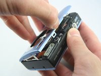
Gently pull off the front cover.
-
Gently pull off the back cover.
I had to remove the screw on the bottom mounting plate to get the front case cover off. The screw closest to the middle. The front plate does have a hole here that the screw goes through
remove both screws - the second holds the back plate
-
-
-
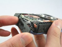
The cases should now be removed.
This can be a bit tricky when reassembling. All of the little tabs around the edge need to snap into their proper places, and there are three cover pieces to manage. Plus, you need to make sure that the camera/video/playback switch is properly engaged with its slider on the circuit board, otherwise you'll need to raise the back panel and reposition everything again.
oh yes , i agree lol
elbala80 -
-
-
-
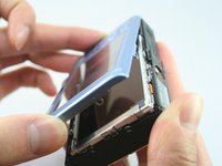
Remove the top-left screw above the LCD screen (0.100 in).
-
Remove the C-shaped plate from the side of the LCD screen.
-
-
-
-
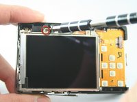
Remove the screw from the top-right of the LCD screen (0.098 in).
-
Remove the L-shaped bar from the right of the LCD screen.
I used this guide for a blue "made in china" version of this camera, as well as a silver "made in japan" version. The L-shaped brackets on either side of the LCD were much easier to remove for the blue one, but I was able to get them out for the silver one also with some additional coaxing. There were more pronounced tabs/notches securing the brackets to the adjacent frame on the silver one.
-
-
-
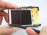
Use the spudger to remove the L-shaped bar from the left-side of the LCD screen.
-
-
crwdns2935267:0crwdne2935267:0Tweezers$4.99
-
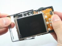
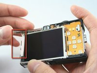
Use tweezers to remove the connector ribbon from the top-left corner above the LCD screen.
There is a hole in the reinforced "plug" end of the LCD cable shown in Step 8. You can use a dental-type pick to remove and replace the plug easily.
-
-
-
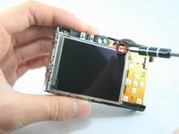
Use a spudger to lift the connector lock (black flap) at the end of the larger LCD connector ribbon on the front side of the camera.
-
Use the tweezers to lift this ribbon.
-
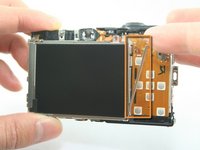
Use the tweezers to gently peel this ribbon from the one underneath it.
-
-
-
The LCD screen should now be removed.
-
-
-
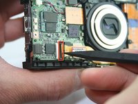
Remove the screw located on the side of the camera (0.072 in).
-
-
-
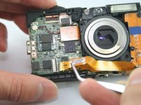
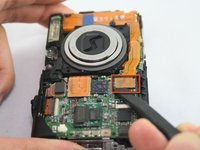
Use the spudger to remove the lens ribbon from the circuit board.
-
Use the spudger to lift the ribbon.
-
-
-
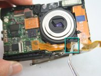
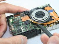
Disconnect the flash assembly ribbon.
-
-
-
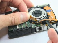
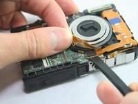
Remove the flash assembly, which includes the capacitor. If it resists, note the small hook on the right side near the bottom.
I had trouble with the small hook here. I found it much easier to first remove the two screws on the back holding this metal piece in place.
-
-
-
The capacitor should now be removed.
-


To reassemble your device, follow these instructions in reverse order.
To reassemble your device, follow these instructions in reverse order.
crwdns2935221:0crwdne2935221:0
crwdns2935229:03crwdne2935229:0
crwdns2915084:0crwdne2915084:0

Cal Poly, Team 3-32, Regan Winter 2011 crwdns2935289:0Cal Poly, Team 3-32, Regan Winter 2011crwdne2935289:0
CPSU-REGAN-W11S3G32
crwdns2931471:03crwdne2931471:0
crwdns2935297:08crwdne2935297:0
crwdns2947412:02crwdne2947412:0
Step 14 The little hook at the bottom that holds the flash assembly in is hard to see. It is part of the bracket that holds the flash in and also forms part of the chassis of the camera. I found that you can gently flex the bracket outward ( away from the flash) to release the hook. After that, the flash unit came right out. Also note, that some flash units you get from electronics scrapers on ebay will have the bracket attached to the flash unit and it needs to be removed before you install the replacement part. It seems obvious but then again...
How much would it be to get this fixed?