crwdns2915892:0crwdne2915892:0
If your flash has burned out or just stopped working, here is how to replace it so you can continue taking great pictures!
crwdns2942213:0crwdne2942213:0
-
-
Turn off your camera.
-
Remove the battery to prevent risk of shock.
-
-
-
Turn off your camera by pressing the power button, located on the top-center of the device.
-
Locate the battery door on the bottom right area of the camera case.
-
Place your finger firmly on the black rubber pad on the battery door and slide the door to the right to open it.
-
Locate the orange battery release button beneath the battery door.
-
Slide the battery release button downward to release the battery.
-
-
-
Remove the two screws located on the left side of the camera case, using the Phillips screwdriver #00 (2.0 mm).
-
-
-
Remove the two screws on the bottom of the camera located near the battery door (Phillips #00 screwdriver) (4.0 mm).
-
-
-
Remove the screw located on the lower right side of the camera case (Phillips #00 screwdriver) (4.0 mm).
-
Remove the HDMI A/V out port cover located on the upper right side of the camera.
-
Remove the screw located just beneath the port cover removed in step 2. (Phillips #00 screwdriver) (2.0 mm).
-
-
-
Remove the back portion of the camera case to reveal the screw located on the top of the case.
-
Remove the screw from the top of camera case, located next to the shutter button (Phillips #00 screwdriver) (1.5 mm).
-
-
-
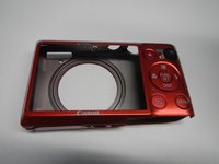
Carefully pry the case apart at the seem, using your fingers.
-
-
-
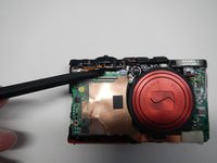
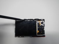
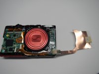
Disconnect the copper ribbon next to the blue port on the motherboard
-
-
-
To remove ribbon cable, gently lift the black tab with a flat head screwdriver. Lift from the top of the camera towards the bottom. This releases the cable. Be gentle, as the cables are fragile.
-
-
-
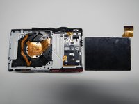
Remove the L shaped bracket around the top and right side of the LCD screen
-
-
-
Insert the flat side of the spudger tool carefully on the top of the LCD screen and lift the screen free
-
-
-
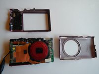
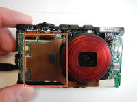
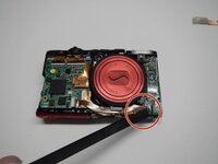
Carefully remove the large copper ribbon on the front of the camera (attached with adhesive pads)
-
-
-
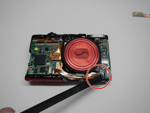
Remove the ribbon wire attached at the bottom right corner of the front of the camera. You do NOT need to remove this from the motherboard.
-
-
-
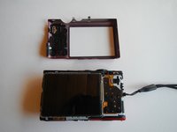
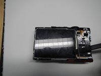
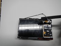
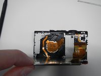
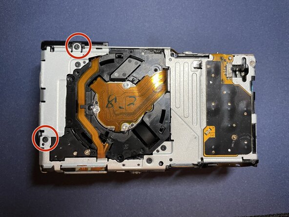
Locate the screws on silver panel that was behind the LCD screen, after removing the screen.
-
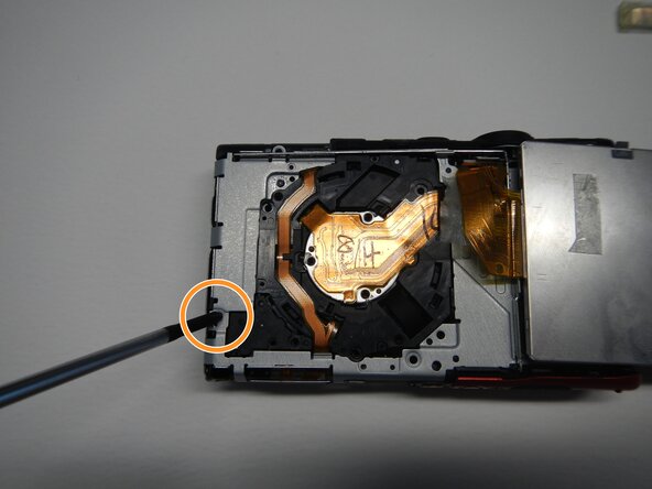
Unscrew the screw on the lower left part of the silver part of the back under where the LCD screen was.
-
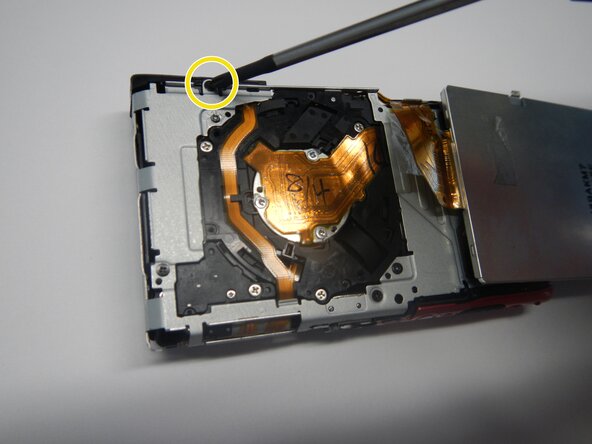
Unscrew the screw on the top of the silver part of the back
-
-
-
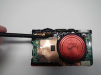
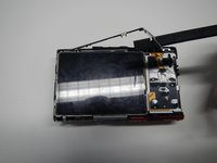
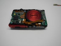
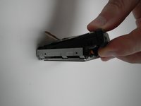
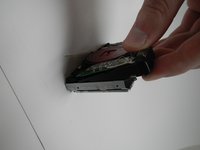
Lift the flash housing up and forward from the top of the camera to carefully remove
-


To reassemble your device, follow these instructions in reverse order. Take your e-waste to an R2 or e-Stewards certified recycler.
To reassemble your device, follow these instructions in reverse order. Take your e-waste to an R2 or e-Stewards certified recycler.
crwdns2935221:0crwdne2935221:0
crwdns2935229:02crwdne2935229:0
crwdns2915084:0crwdne2915084:0

Michigan Tech, Team 5-6, Lauer Spring 2014 crwdns2935289:0Michigan Tech, Team 5-6, Lauer Spring 2014crwdne2935289:0
MTU-LAUER-S14S5G6
crwdns2931471:03crwdne2931471:0
crwdns2935297:06crwdne2935297:0