crwdns2915892:0crwdne2915892:0
This guide will attempt to show the user how to safely remove and replace the keyboard without damaging any of the surrounding components.
crwdns2942213:0crwdne2942213:0
-
-
Use an opening tool to pry up the small rubber cover on the upper right corner of the RAM access door.
-
-
-
Remove the 5.3 mm Phillips #00 screw securing the RAM access door.
-
-
-
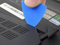
Insert the point of an opening pick in the seam near the top right corner of the RAM access door and gently pry the door up slightly.
-
The door is held in place by small clips around its edges. Pry until you feel the nearest clips release.
-
-
-
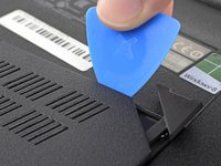
Insert the wide edge of an opening pick into a new part of the seam between the door and the computer.
-
Pry the door up to release the clips closest to the pick.
-
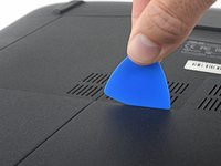
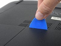
Continue to slide the pick along the seam all the way around the door, prying as you go, until all the clips holding the door down have been released.
-
-
-
-
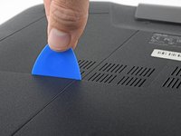
Remove the 5.2 mm Phillips #00 screw securing the optical drive.
-
-
-
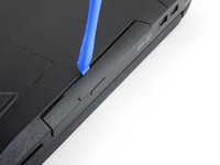
Insert an opening tool into the gap between the optical drive and the laptop.
-
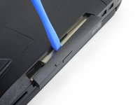
Pry the optical drive straight out of the laptop.
-
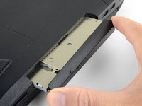
Remove the optical drive.
-
-
-
Remove the ten 5.2 mm screws holding the main panel in place, highlighted in the photo, with a Phillips screwdriver.
-
Remove the four 5.2 mm screws underneath the center panel, highlighted in the photo, with a Phillips screwdriver.
-
-
-
Remove the two 6.8 mm screws underneath to back panel, highlighted in the photo, with a Phillips screwdriver.
-
-
-
Use the plastic opening tool to pry the keyboard from the base of the laptop.
-
-
-
Unlatch and disconnect each of the four ZIF connectors.
-
The keyboard is now fully disconnected and you are now free to lift the keyboard away from the computer.
-


To reassemble your device, follow these instructions in reverse order.
To reassemble your device, follow these instructions in reverse order.
crwdns2935221:0crwdne2935221:0
crwdns2935229:04crwdne2935229:0
crwdns2915084:0crwdne2915084:0

USF Tampa, Team 2-1, Sullivan Fall 2016 crwdns2935289:0USF Tampa, Team 2-1, Sullivan Fall 2016crwdne2935289:0
USFT-SULLIVAN-F16S2G1
crwdns2931471:04crwdne2931471:0
crwdns2935297:020crwdne2935297:0
crwdns2947410:01crwdne2947410:0
Great work, but you are missing the last few steps of the replacement as all you are showing is how to remove the upper assembly