crwdns2915892:0crwdne2915892:0
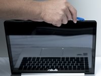
If your ASUS VivoBook S400C has a broken touchscreen or continues to have issues even after going through the touch screen trouble shooting guide to rule out any software issues, use this guide to replace it. Before you begin, make sure the laptop is completely turned off and the battery has been removed.
Warning: If the glass display is completely shattered, please remain safe by following the directions here on how to tape over any glass and prevent being hurt.
Note: Make sure the new screen has the same resolution and size as the original screen. You may get some help on finding this information by visiting this website.
crwdns2942213:0crwdne2942213:0
-
-
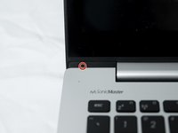
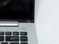
Flip the device over and remove the ten 5.7 mm screws with a Phillips #0 screwdriver.
-
-
-
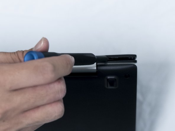
Use a spudger or your fingers to go around and lift the edges and release the back panel.
-
-
-
Using a spudger, lift up the plug connecting the battery to the motherboard.
-
-
-
Use a spudger to release the cables from the wifi card.
-
-
-
Remove the singular 3.8 mm screw with a Phillips #0 screwdriver.
-
-
-
-
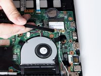
Lift up the black tape.
-
-
-
Peel the clear tape on the connector and pull the connector out.
-
-
-
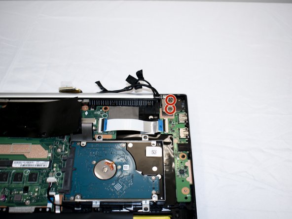
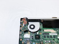
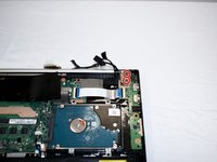
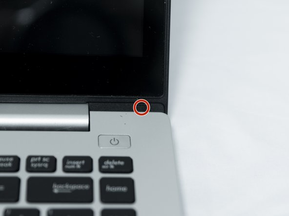
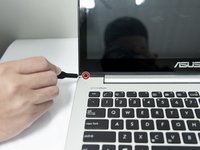
Using a Phillips #0 screwdriver, remove the four 6 mm hinge screws.
-
-
-
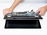
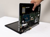
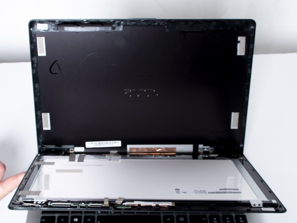
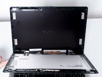
Lift the bottom (keyboard) portion of the laptop up holding closely to the hinge. Keep rotating along the hinge until the bottom portion becomes detached.
-
After rotating open to about a 90 degree angle, lift the bottom portion outwards.
-
-
-
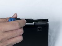
Using a #3 flathead screwdriver, pull the black tabs covering the screws.
-
-
-
With a Phillips #0 screwdriver, remove the two 3.8 mm screws holding the bezel in place.
-
-
-
Use a plastic opening tool to go around the edges and release the bezel panel along the sides, switching to a #3 flathead screwdriver along the bottom edges.
-
-
-
Peel the clear tape on the connector and pull the connector out.
-
-
-
Release the latch and unclip the ribbon cables from the top antenna daughterboard.
-
Gently pull to the right toward the center of the panel and lift it up and out.
-
-
-
Pull out the smaller microphone daughterboard with a spudger.
-
-
-
Carefully remove the tape and unravel the wiring fixing the daughterboards to the front bezel and remove the bezel from the panel.
-


To reassemble your device, follow these instructions in reverse order.
crwdns2935221:0crwdne2935221:0
crwdns2935227:0crwdne2935227:0
crwdns2935287:0crwdne2935287:0

UC Santa Barbara, Team S4-G4, Bator Fall 2019 crwdns2935289:0UC Santa Barbara, Team S4-G4, Bator Fall 2019crwdne2935289:0
UCSB-BATOR-F19S4G4
crwdns2931471:03crwdne2931471:0
crwdns2935297:04crwdne2935297:0
crwdns2947412:03crwdne2947412:0
I would advise you not to use this guide. Specifically, following step 15 will result in damage to your display bezel and/or the display housing. The LCD/touch screen assembly slides down to release it from the latches holding it in place. If you simply pry it apart without sliding it down, you will break the retainers that hold it together.
I found this out the hard way, by following this guide. I'm in the process of rewriting the entire guide with the correct procedure for removing the screen assembly from the housing, which should be done soon. When it's complete, the "In Progress" flag will be removed.
The new guide is complete. Please, for the sake of your display, use it instead of this one.