crwdns2933423:0crwdne2933423:0
crwdns2947577:0crwdnd2947577:0crwdne2947577:0

08. LCD screen and PSU

crwdns2869540:0crwdne2869540:0: 9

crwdns2959988:0crwdne2959988:0

crwdns2959990:0crwdne2959990:0
4
crwdns2959992:0crwdne2959992:0
9
crwdns2959994:0crwdne2959994:0
9
crwdns2959996:0crwdne2959996:0
9
crwdns2955950:0crwdne2955950:0: 0

crwdns2959998:0crwdne2959998:0

crwdns2960000:0crwdne2960000:0
crwdns2959984:0crwdne2959984:0: 0

crwdns2959956:0crwdne2959956:0

crwdns2959986:0crwdne2959986:0: 0

crwdns2959958:0crwdne2959958:0

crwdns2955944:0crwdne2955944:0: crwdns2931273:0crwdne2931273:0
crwdns2955970:0crwdne2955970:0: crwdns2937801:0crwdne2937801:0
08. LCD screen and PSU
    1. 08. LCD screen and PSU, LCD preparation: crwdns2935265:01crwdnd2935265:01crwdnd2935265:03crwdne2935265:0 08. LCD screen and PSU, LCD preparation: crwdns2935265:01crwdnd2935265:02crwdnd2935265:03crwdne2935265:0 08. LCD screen and PSU, LCD preparation: crwdns2935265:01crwdnd2935265:03crwdnd2935265:03crwdne2935265:0
      • Slide the lcd_support_a and lcd_support_b onto the LCD control board.

      • Verify that the orientation is correct.

      • Assemble the LCD cover on the LCD control board.

      • Adjust the position of the lcd_support_a and lcd_support_b in order to insert the LCD control board on the cover.

      • The LCD control board must clip into the LCD cover.

      • Secure the LCD control board with 2x M3x10 screws (reused from your Original Prusa).

      • Put the LCD knob back in place.

      crwdns2952109:0crwdne2952109:0

      crwdns2917038:0crwdne2917038:0

    2. 08. LCD screen and PSU, LCD installation: crwdns2935265:02crwdnd2935265:01crwdnd2935265:02crwdne2935265:0 08. LCD screen and PSU, LCD installation: crwdns2935265:02crwdnd2935265:02crwdnd2935265:02crwdne2935265:0
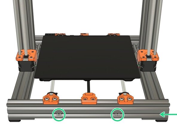
      • Slide 2x t-nuts in the bottom front of your frame.

      • Attach the LCD using 2x M5x10 screws.

      crwdns2952109:0crwdne2952109:0

      crwdns2917038:0crwdne2917038:0

    3. 08. LCD screen and PSU, PSU upper mount preparation: crwdns2935265:03crwdnd2935265:01crwdnd2935265:03crwdne2935265:0 08. LCD screen and PSU, PSU upper mount preparation: crwdns2935265:03crwdnd2935265:02crwdnd2935265:03crwdne2935265:0 08. LCD screen and PSU, PSU upper mount preparation: crwdns2935265:03crwdnd2935265:03crwdnd2935265:03crwdne2935265:0
      • We are going to test your dexterity in this step :)

      • Prepare the following hardware:

      • 2x M4x10 screws (reused from your Original Prusa).

      • 2x psu_upper_mount.

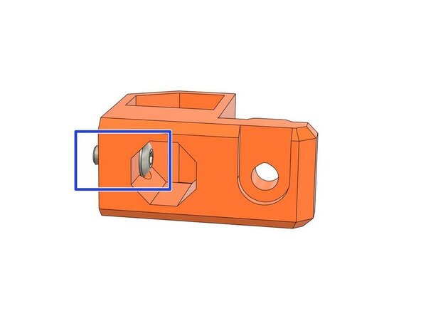
      • Place the M4x10 screw in the internal hole of the psu_upper_mount.

      • If you struggle with this, you can insert a finger in the biggest hole (check the 3rd image). doing this makes it easier for you to hold and guide the screw into the hole.

      • Insert the other M4x10 in the remaining psu_upper_mount.

      • Now try not to lose the screws until we are bolting them on the PSU :D

      crwdns2952109:0crwdne2952109:0

      crwdns2917038:0crwdne2917038:0

    4. 08. LCD screen and PSU, PSU type: crwdns2935265:04crwdnd2935265:01crwdnd2935265:02crwdne2935265:0 08. LCD screen and PSU, PSU type: crwdns2935265:04crwdnd2935265:02crwdnd2935265:02crwdne2935265:0
      • The next steps are for the Prusa silver PSU only.

      • If you have the Prusa black PSU, go to step 11

      • If you don't know which PSU you have, please check the second image.

      • Prusa black PSU

      • Prusa silver PSU

      • Image copyright: Prusa Research

      crwdns2952109:0crwdne2952109:0

      crwdns2917038:0crwdne2917038:0

    5. 08. LCD screen and PSU, PSU upper mount assembly - Silver PSU: crwdns2935265:05crwdnd2935265:01crwdnd2935265:02crwdne2935265:0 08. LCD screen and PSU, PSU upper mount assembly - Silver PSU: crwdns2935265:05crwdnd2935265:02crwdnd2935265:02crwdne2935265:0
      • Attach the psu_upper_mounts to the silver PSU body. Fully tighten the M4 screws, ensuring that the PSU mounts are properly positioned and aligned .

      • Verify that the psu_upper_mounts are aligned with the PSU

      crwdns2952109:0crwdne2952109:0

      crwdns2917038:0crwdne2917038:0

    6. 08. LCD screen and PSU, PSU lower mount assembly - Silver PSU: crwdns2935265:06crwdnd2935265:01crwdnd2935265:03crwdne2935265:0 08. LCD screen and PSU, PSU lower mount assembly - Silver PSU: crwdns2935265:06crwdnd2935265:02crwdnd2935265:03crwdne2935265:0 08. LCD screen and PSU, PSU lower mount assembly - Silver PSU: crwdns2935265:06crwdnd2935265:03crwdnd2935265:03crwdne2935265:0
      • The psu_lower_mount in this step is slightly different for MK2(S)/MK2.5(S) and MK3(S) but they have the same functionality and assembly.

      • Take the psu_lower_mount and insert a square nut.

      • Slide 1x t-nut into the lower channel of the rear extrusion, from the right side of the frame.

      • Assemble the psu_lower_mount with 1x M5x10 screw. Don't tighten fully yet as it will need some repositioning.

      crwdns2952109:0crwdne2952109:0

      crwdns2917038:0crwdne2917038:0

    7. 08. LCD screen and PSU, PSU installation - Silver PSU: crwdns2935265:07crwdnd2935265:01crwdnd2935265:03crwdne2935265:0 08. LCD screen and PSU, PSU installation - Silver PSU: crwdns2935265:07crwdnd2935265:02crwdnd2935265:03crwdne2935265:0 08. LCD screen and PSU, PSU installation - Silver PSU: crwdns2935265:07crwdnd2935265:03crwdnd2935265:03crwdne2935265:0
      • Rotate the frame to the right side. Carefully guide the extruder to the right. Do not let it slide freely into the x-ends..

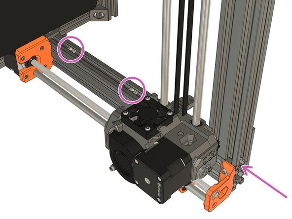
      • Slide 2x t-nuts into the extrusion from the top of the frame, as shown.

      • Position the PSU and secure it with 2x M5x10 screws. Do not tighten them fully yet.

      crwdns2952109:0crwdne2952109:0

      crwdns2917038:0crwdne2917038:0

    8. 08. LCD screen and PSU, PSU installation - Silver PSU: crwdns2935265:08crwdnd2935265:01crwdnd2935265:03crwdne2935265:0 08. LCD screen and PSU, PSU installation - Silver PSU: crwdns2935265:08crwdnd2935265:02crwdnd2935265:03crwdne2935265:0 08. LCD screen and PSU, PSU installation - Silver PSU: crwdns2935265:08crwdnd2935265:03crwdnd2935265:03crwdne2935265:0
      • Secure the bottom of the PSU with an M3 screw reused from your Original Prusa, do not tighten fully yet. This screw has a different length depending on which Prusa model you have:

      • MK2(S) or MK2.5(S): length can be 18mm or 25mm (both are compatible with the psu_lower_mount).

      • MK3(S): 10mm long.

      • Verify that the PSU cables are not pinched and pass under the Y axis smooth rod.

      • Adjust the PSU position to be flush with the extrusion at the rear of the frame.

      • Fully tighten evenly, incrementally and in turn the screws of psu_lower_mount and psu_upper_mount.

      • Verify that the PSU cables aren't pinched and pass under the Y axis smooth rod.

      crwdns2952109:0crwdne2952109:0

      crwdns2917038:0crwdne2917038:0

    9. 08. LCD screen and PSU, Next chapter: crwdns2935265:09crwdnd2935265:01crwdnd2935265:01crwdne2935265:0
      crwdns2952109:0crwdne2952109:0

      crwdns2917038:0crwdne2917038:0

    10. 08. LCD screen and PSU, PSU type: crwdns2935265:010crwdnd2935265:01crwdnd2935265:02crwdne2935265:0 08. LCD screen and PSU, PSU type: crwdns2935265:010crwdnd2935265:02crwdnd2935265:02crwdne2935265:0
      • The next steps are for the Prusa black PSU only.

      • If you have the Prusa silver PSU, go to step 5

      • If you don't know which PSU you have, please check the second image.

      • Prusa black PSU

      • Prusa silver PSU

      • Image copyright: Prusa Research

      crwdns2952109:0crwdne2952109:0

      crwdns2917038:0crwdne2917038:0

    11. 08. LCD screen and PSU, PSU upper mount assembly - Black PSU: crwdns2935265:011crwdnd2935265:01crwdnd2935265:02crwdne2935265:0 08. LCD screen and PSU, PSU upper mount assembly - Black PSU: crwdns2935265:011crwdnd2935265:02crwdnd2935265:02crwdne2935265:0
      • Attach the psu_upper_mounts to the black PSU body. Fully tighten the M4 screws, ensuring that the PSU mounts are properly positioned and aligned .

      • Verify that the psu_upper_mounts are aligned with the PSU

      crwdns2952109:0crwdne2952109:0

      crwdns2917038:0crwdne2917038:0

    12. 08. LCD screen and PSU, PSU lower mount assembly - Black PSU: crwdns2935265:012crwdnd2935265:01crwdnd2935265:03crwdne2935265:0 08. LCD screen and PSU, PSU lower mount assembly - Black PSU: crwdns2935265:012crwdnd2935265:02crwdnd2935265:03crwdne2935265:0 08. LCD screen and PSU, PSU lower mount assembly - Black PSU: crwdns2935265:012crwdnd2935265:03crwdnd2935265:03crwdne2935265:0
      • Take the psu_lower_mount and insert a square nut.

      • Slide 1x t-nut into the top channel of the rear extrusion, from the right side of the frame.

      • Assemble the psu_lower_mount with 1x M5x10 screw. Don't tighten fully yet as it will need some repositioning.

      crwdns2952109:0crwdne2952109:0

      crwdns2917038:0crwdne2917038:0

    13. 08. LCD screen and PSU, PSU installation - Black PSU: crwdns2935265:013crwdnd2935265:01crwdnd2935265:03crwdne2935265:0 08. LCD screen and PSU, PSU installation - Black PSU: crwdns2935265:013crwdnd2935265:02crwdnd2935265:03crwdne2935265:0 08. LCD screen and PSU, PSU installation - Black PSU: crwdns2935265:013crwdnd2935265:03crwdnd2935265:03crwdne2935265:0
      • Rotate the frame to the right side. Carefully guide the extruder to the right. Do not let it slide freely into the x-ends..

      • Slide 2x t-nuts into the extrusion from the top of the frame, as shown.

      • Position the PSU and secure it with 2x M5x10 screws. Do not tighten them fully yet.

      crwdns2952109:0crwdne2952109:0

      crwdns2917038:0crwdne2917038:0

    14. 08. LCD screen and PSU, PSU installation - Black PSU: crwdns2935265:014crwdnd2935265:01crwdnd2935265:03crwdne2935265:0 08. LCD screen and PSU, PSU installation - Black PSU: crwdns2935265:014crwdnd2935265:02crwdnd2935265:03crwdne2935265:0 08. LCD screen and PSU, PSU installation - Black PSU: crwdns2935265:014crwdnd2935265:03crwdnd2935265:03crwdne2935265:0
      • Remove the PSU cover (with Prusa logo) by unscrewing the 2x M3x10 screws.

      • Take an extra M3x10 (reused from your Original Prusa) screw and secure the PSU to the psu_lower_mount. Do not tighten fully yet.

      • Verify that the PSU cables are not pinched and that they go out of the back of the PSU and pass under the Y axis smooth rod.

      • Verify that the PSU cables are not pinched and are routed correctly.

      crwdns2952109:0crwdne2952109:0

      crwdns2917038:0crwdne2917038:0

    15. 08. LCD screen and PSU, PSU installation - Black PSU: crwdns2935265:015crwdnd2935265:01crwdnd2935265:02crwdne2935265:0 08. LCD screen and PSU, PSU installation - Black PSU: crwdns2935265:015crwdnd2935265:02crwdnd2935265:02crwdne2935265:0
      • Adjust the PSU position to be flush with the extrusion at the rear of the frame.

      • Fully tighten evenly, incrementally and in turn the screws of psu_lower_mount and psu_upper_mount.

      • Reassemble the PSU cover with 2x M3x10 screws (reused from your Original Prusa).

      • Verify again that PSU cables aren't pinched and are correctly routed.

      crwdns2952109:0crwdne2952109:0

      crwdns2917038:0crwdne2917038:0

    16. 08. LCD screen and PSU, Next chapter: crwdns2935265:016crwdnd2935265:01crwdnd2935265:01crwdne2935265:0
      crwdns2952109:0crwdne2952109:0

      crwdns2917038:0crwdne2917038:0

crwdns2935217:0crwdne2935217:0

crwdns2935221:0crwdne2935221:0

Greg Bear

crwdns2935283:011/04/26crwdne2935283:0

8.773 crwdns2915208:0crwdne2915208:0

crwdns2935297:035crwdne2935297:0

crwdns2947412:00crwdne2947412:0

crwdns2917038:0crwdne2917038:0

crwdns2936625:0crwdne2936625:0:

crwdns2936751:024crwdne2936751:0 4

crwdns2936753:07crwdne2936753:0 9

crwdns2936753:030crwdne2936753:0 9

crwdns2959996:0crwdne2959996:0 9