crwdns2933423:0crwdne2933423:0

Battery won't charge.

So I just got my robot vacuum back after lending it to my brother.

Turned out it stopped working a while ago.

When I got it back I started to diagnose it.

The first thing I noticed was, when it's docked in the charginstation, it turns on and I can adopt it into the smart things app. The battery read 0% and no matter how long it charges it wouldn't go up.

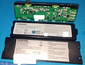
So I started by disassembling the battery down to its individual cells. Turned out 5 out if 6 cells were completely dead (absolute 0 volts).

So I ordered some new cells and put the battery back together. The battery now shows 21,7 volts. But it still doesn't want to run outside the chargingstation.

When I use a multimeter on the battery, while it's connected to the chargingstation it shows about 25 volts on d+ to d- (the plugs from the vacuum to the PCB on the battery). And still 21,7 volts on b+ to b- (the spot welded tin to the battery). It has now charged for about 2 hours and it's still about 37% charged (so not getting charged).

I've tried to put the PCB under an thermal camera to see if anything gets hot, but it doesn't. Even with it plugged into the chargingstation, without the chargingstation or it disconnected from the robot. I've also tried to connect 21 volts 1 a with a powersupply connected both on d+ to d- and on b+ to b-, yet nothing gets hot.

Anyone have any idea on how I could fix this?

I'm pretty new to this stuff, but I do watch some youtubers like NorthridgeFix and TronicFix so I have some general idea.

Should I disconnect the cells again and maybe try injecting voltage over some of the chips on the PCB or check the resistance on some of the caps? If so i would love some guidence. I don't have a chip programmer yet, but I will order one sooner or later, if needed.

Image of the PCB here:

https://imgur.com/a/eqJpynu

Block Image

I'm also working on a guide on the disassembly of the batter here (ask and ill add you in order to view):

Disassembling Samsung Vacuum Battery VCA-RBT80 VR30T80313W/WA

crwdns2934089:0crwdne2934089:0 crwdns2934093:0crwdne2934093:0

crwdns2934109:0crwdne2934109:0

crwdns2889612:0crwdne2889612:0 1

crwdns2944067:06crwdne2944067:0:

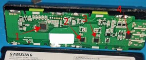
@cyrex86 since your guide is not yet made public, we can't preview unless you "allow" it. This does sound like a battery issue. Are you using all new cells? You have the same capacity cells as well as made sure they are fairly well balanced in regards to their charge? Not sure about this particular battery but it is possible that there are issues with the EEPROM on the battery that may have to be reset or reprogrammed. Nasty trick from the OEM's to make us have to buy their batteries vs. rebuilding. Let's see if we can find out more about that possibility. Looking forward to seeing your guide as well as your future repairs. It is appreciated.

Repair is War on Entropy!

crwdns2934271:0crwdnd2934271:0crwdne2934271:0

@oldturkey03 Ah darn I thought the link I made would make it accessible through the link. I'll make it public but just know it's not finished just yet. I was gonna take picture of the cutting tool I used etc to make it more filling.

crwdns2934271:0crwdnd2934271:0crwdne2934271:0

@oldturkey03 The cells are all brand new (Atleast as much as we can thrust AliExpress), the exact same value and charged to their storage voltage when I got them (about 40 ish %). I put them into a charger (Liitokala, for about 10 minutes) that shows % and current voltage etc. The cells aren't perfectly balanced, but I would say they are within 5% of each other.

This is a link to the cells:

https://www.aliexpress.com/item/10050051...

And here are some pictures of the cells

https://imgur.com/a/OkaM7Mi

Old vs New cells:

https://imgur.com/a/Fg6yixH

crwdns2934271:0crwdnd2934271:0crwdne2934271:0

Also, any reccomandations on an EEPROM? I was planning on getting this:

https://a.aliexpress.com/_EHHnFSY

Is this something I need, and is this even an EEPROM? 😋🙃

crwdns2934271:0crwdnd2934271:0crwdne2934271:0

@cyrex86 I think you can actually add users to see your guide before making it public. Great job on pre-charging the cells, and that is the way I manage new cells as well. do my batteries. As for the programmer, it might help if you can identify the EEPROM on your board. There might just be a way to "reset" it and with some luck there might even be a datasheet that could help with that.

crwdns2934271:0crwdnd2934271:0crwdne2934271:0

crwdns2934273:01crwdne2934273:0

crwdns2934285:0crwdne2934285:0

crwdns2933315:02crwdne2933315:0

@cyrex86 I would expect an EEPROM to have either 6 or most commonly 8 legs. See if you can make out any identifiers on these IC's. #4 looks like a voltage regulator and #1 like the charge controller.

Block Image

The issue sound so much like a locked battery.... SDA and SCL means that there is definitely some communication between the battery and the vacuum ¯\_(ツ)_/¯ :-)

crwdns2934105:0crwdne2934105:0

crwdns2889612:0crwdne2889612:0 0

crwdns2944067:042crwdne2944067:0:

@oldturkey03 yeah. I did some asking with an AI yesterday and it basically said that when the batteries went bad the vacuum sendt a "red flag" to the batterie's PCB EEPROM. And that this is a known problem with large manufacturers like Samsung, Apple and Nikon. And in order to remove the "red flag" one needs specialized hardware and software and an high understanding in coding in order to reverse engineer the code to remove the "red flag". Changing the cells and doing a "hard reset" of the robot isn't enough. Also the AI scanned the SparkFun forum, that does theese kind if things, and it came to the conclusion that many have tried, but no one has been successful yet.

But hey, maybe we can crack it together 😁

Here are the markings on the IC's.

1 (48 legs):

240080

10610G

D

2 and 3 (8 legs):

6N3R4C

04934E

4 (2 wide "legs"):

GFR

There us no other marking than this, like an brand mark or anything, Indicating theese are custom made for Samsung, atleast according to AI (i used Gemeni).

crwdns2934271:0crwdnd2934271:0crwdne2934271:0

@oldturkey03 Also the link to the hardware I sendt in the original comment you made on the post, is not what I need since that one is for completely rewriting the code on the IC (meaning i then need the original code, somehow, in order to "roll back" the code), atleast according to the AI I asked:

https://a.aliexpress.com/_EHHnFSY

But the AI said this is the hardware I need (this just reads the code and I, with the right software and code understanding, will be able to unflag the "red flag":

https://a.aliexpress.com/_EQmcZoy

Or

https://a.aliexpress.com/_EG5brYy

Is the AI trolling me? Or is this right? 😅

Also if u want I can put the battery under the microscope and take higher resolution pictures of the IC's if you'd like 🙂 Maybe you see something I don't 😄

crwdns2934271:0crwdnd2934271:0crwdne2934271:0

@oldturkey03 Will you look at that, I missed something 😁 It was GFR not CFR on 4, and 1 had a small D in the bottom left corner 😅

https://imgur.com/a/TXk6b7u

I edited the first post to be correct.

Also this is what Gemeni said about what the guys on the forum that has attempted what we are trying to do:

"Advanced users on sites like the SparkFun forum have attempted exactly what you are trying to do. They have identified pinouts and tried to force a reset by connecting various pins (like RESETOUT and AFE), without success. It is a highly complex chip that doesn't give up its lock easily."

crwdns2934271:0crwdnd2934271:0crwdne2934271:0

@cyrex86 #2 and #3 are indeed N-channel MOSFETs #4 is a TVS diode #1 is still a mystery. The "D" is most likely a makers mark. Time to do some snooping. Why do I think that this is somehow solvable by using the SDA/SCL pins :-) We need to find a way to "read" the board.........

crwdns2934271:0crwdnd2934271:0crwdne2934271:0

@oldturkey03 Oh are those mosfets? I thought mosfets had a big drain to ground, but maybe I'm mixing it with something else. As i said I'm still in the learning phase on this stuff 😁 hopefully i get some more experience next year since I then, hopefully, start my studying to become an electrical engineer 😊

Yeah, im also wondering how we can read theese pins 😅 should I just go and order any of the three items I linked? If you don't want to press the links, then that is understandable. If you want, I can post the items "headline". I can also confirm that the last two items I posted has SCL/SDA connection headers.

crwdns2934271:0crwdnd2934271:0crwdne2934271:0

crwdns2934275:037crwdne2934275:0

crwdns2934285:0crwdne2934285:0

Your robot vacuum battery shows good cell voltage now, but the BMS board is likely locked or damaged, so it won’t deliver power off the dock.
You may need to replace or reset the BMS because injecting voltage or probing chips usually won’t revive a locked protection circuit.

crwdns2934105:0crwdne2934105:0

crwdns2889612:0crwdne2889612:0 0

crwdns2947414:01crwdne2947414:0:

@lalan45 Hi and welcome to the discussion 😊 Yes, we figured as much in the other answer. The plan was to try to communicate with the BMS with a CP2112 or a FT232H USB to SMBUS I²C communicator, but silly old me managed to bridge two pins on the RAJ240080 controller, when trying to remove the glue on the IC, and it burnt since i didnt remove the cells when fooling around with the BMS, so bye bye project on rewriting the controller. So next attempt will be to just replace the RAJ240080 IC. But do you think it would be possible to simply reset it somehow without a I²C communicator/replacing the IC? Like I don't know, like bridge two jumpers or something (like we usually do on a motherboard in order to clear /reset bios)?

crwdns2934271:0crwdnd2934271:0crwdne2934271:0

crwdns2934285:0crwdne2934285:0

crwdns2934229:0crwdne2934229:0

CyReX crwdns2934231:0crwdne2934231:0
crwdns2936625:0crwdne2936625:0:

crwdns2936751:024crwdne2936751:0 12

crwdns2936753:07crwdne2936753:0 58

crwdns2936753:030crwdne2936753:0 275

crwdns2942667:0crwdne2942667:0 275