crwdns2933423:0crwdne2933423:0

Mid-range Bluetooth noise-canceling over-ear headphones by SONY.

nothing happens when I connect the charger

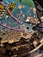
I found this pair of headphones at a flea market. I opened them and found this improvisation on the power jack. Can you tell me if it was done correctly? I also replaced the battery because it was no longer good and the headphones work but when I try to connect them to charge nothing happens.

Block Image
Block Image
crwdns2934089:0crwdne2934089:0 crwdns2934093:0crwdne2934093:0

crwdns2934109:0crwdne2934109:0

crwdns2889612:0crwdne2889612:0 0

crwdns2944067:05crwdne2944067:0:

Sounds like you’ve done some solid detective work already.

crwdns2934271:0crwdnd2934271:0crwdne2934271:0

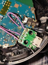
@dani88790 post a better picture of the USB board. What is the voltage at the solder points on your headphones circuit board, when you plug your charger in?

crwdns2934271:0crwdnd2934271:0crwdne2934271:0

@oldturkey03 The voltage is 5.12 at the solder point of the bord of jack an same on the solder on the headset bord

crwdns2934271:0crwdnd2934271:0crwdne2934271:0

@dani88790 I wonder if your charging circuitry is "not turning on" When you connect the charger, what voltage do you get right on the battery connector? If that voltage does not increase when you connect the charger, you know that there is something that does not tell the power management IC to let the battery charge

crwdns2934271:0crwdnd2934271:0crwdne2934271:0

@oldturkey03 thanks for this tip. when I have time I will test this suggestion and leave the result here

crwdns2934271:0crwdnd2934271:0crwdne2934271:0

crwdns2934285:0crwdne2934285:0

crwdns2933313:01crwdne2933313:0

that appears correctly connected to the USB. The 2 outside pins are 5V and ground. However, without tracing the circuit, one can't tell if the polarity is correct on the board.

crwdns2934105:0crwdne2934105:0

crwdns2889612:0crwdne2889612:0 0

crwdns2944067:03crwdne2944067:0:

Thanks for the answer. Can you explain me haw to do that?

crwdns2934271:0crwdnd2934271:0crwdne2934271:0

those pics are better. It appears like it is properly connected. Generally, the highest failure part is power diodes, then transistors. Those are usually easy to test in circuit with a diode function of a DVM. Any device with more than 3 terminals would require a schematic, power up testing, and maybe a scope.

crwdns2934271:0crwdnd2934271:0crwdne2934271:0

Thanks for the answer . I do not have this equipment and in my city I don't have repair center with something like this. If a simple solution it's not available I will abandon this repair project

crwdns2934271:0crwdnd2934271:0crwdne2934271:0

crwdns2934285:0crwdne2934285:0

crwdns2934229:0crwdne2934229:0

Dani crwdns2934231:0crwdne2934231:0
crwdns2936625:0crwdne2936625:0:

crwdns2936751:024crwdne2936751:0 6

crwdns2936753:07crwdne2936753:0 60

crwdns2936753:030crwdne2936753:0 60

crwdns2942667:0crwdne2942667:0 60