crwdns2933423:0crwdne2933423:0

Over the range stainless steel microwave oven. First released September 2013

No power after 20amp fuse blown and replaced

Hello, second time I've tried to fix our microwave. First time successful... one of the door switches failed and blew the 20a fuse. I was able to replace the door switch and fuse and it worked again for over a year now.

This time, fuse blew again so I took it apart. The three door switches all test okay: clicking correctly and continuity test check out whether normally open or normally closed. Replaced the 20a fuse again, but when plugged back in there's no power to the control panel. Fuse is good and there's continuity across the fuse to the other contact.

The two thermal cut offs directly behind the control panel test ok, but I haven't been able to reach the "Cavity Thermostat Cutout" for testing. The unit shouldn't have reached anywhere near the 230F temperature listed to blow that, but I guess it's still possible this has failed.

Other possibilities? I see a H.V. Trans Fuse listed and it could possibly be a bad Magnetron. These or possibly a new control board?

I'm reaching the limit of my abilities as a non-licensed/weekend hack/cheapskate just trying to keep a microwave running. Time to just spring for a new one and play the "disposable appliance" game?

Thanks for any insight

Update (11/04/25)

Block Image

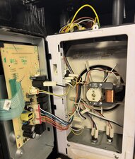
Was trying to put a picture up too

crwdns2934089:0crwdne2934089:0 crwdns2934093:0crwdne2934093:0

crwdns2934109:0crwdne2934109:0

crwdns2889612:0crwdne2889612:0 1
crwdns2944067:02crwdne2944067:0

I don't have much insight, Microwaves are not my forte, but I wanted to commend your dedication. Usually I would have said check fuses since that's about as far as I go into microwaves but you're well beyond that. :/

crwdns2934271:0crwdnd2934271:0crwdne2934271:0

@mrerik "Time to just spring for a new one and play the "disposable appliance" game" no way! I know there are some pretty smart people that are going to be looking at this. Let's put our heads together and get this fixed. Patience ;-)

crwdns2934271:0crwdnd2934271:0crwdne2934271:0

crwdns2934285:0crwdne2934285:0

crwdns2933313:01crwdne2933313:0

crwdns2934057:0crwdne2934057:0

Hi @mrerik

Here's the mini manual for the microwave.

Power is fed from the 20A fuse via three thermal cut outs to the LV transformer on the control board i.e. cavity thermal cutout, magnetron thermal cut out and bottom thermal cutout.

Check if power is getting to the magnetron cutout or bottom thermal cutout. If it is then the cavity thermal cutout is OK.

If it's not getting to the magnetron cutout, the cavity cutout may be the problem.

If it is getting to the bottom thermal cutout, check if the power is reaching the control board - see schematic for connection points.

If it is check for any damage on the board

If you don't like testing for AC power, unplug the oven's power cord from the wall outlet and use an Ohmmeter to test the path from the power cord plug's Active pin or the 20A fuse and prove continuity to the thermal cutouts that you can reach easily through, to the board connector pin #1 (connects to the LV transformer - pin #3 other side of LV transformer goes to the Neutral pin of the power cord plug)

Hopefully you've remembered to short out the HV capacitor to discharge it, before working inside the oven. :-)

crwdns2934105:0crwdne2934105:0

crwdns2889612:0crwdne2889612:0 2

crwdns2944067:05crwdne2944067:0:

Thanks so much @jayeff for all your input on the site!

First off, the HV Capicitor is behind the fan shroud I’ve been unable to take out so far. I’ve had the unit unplugged overnight so hopefully that’s drained the capacitors for my initial unplugged tests.

The Magnetron TCO is also behind this fan shroud, so haven’t been able to directly check that yet.

I was able to check the Cavity TCO and it has continuity. The Bottom TCO has power and reads continuous. The Hood TCO is getting power (except I believe this one is normally open so it doesn’t show continuous right now.)

Between the ground screw and pin#1 it’s showing 1.35V and pin#3 is around 12V (11.5-12.5V different times I checked.) According to the mini manual, these should be 5V, so that could be user error? Update: between the 20A fuse and each pin, I see 120V.

Continuity test: pin#3 is continuous with the power cord plug. Pin#1 is not continuous with the power cord plug.

The Hood TCO is continuous with the power cord plug.

The Bottom TCO isn’t

crwdns2934271:0crwdnd2934271:0crwdne2934271:0

Ran out of room to type, but my brain is hurting from all these tests.

I’m really trying not to uninstall this over-the-range microwave to get this figured out, but looks like that might be needed for the next steps. Let me know if you have any more input on this puzzle!

crwdns2934271:0crwdnd2934271:0crwdne2934271:0

@mrerik

Check for continuity between the bottom TCO and pin #1 as normally there should be 120V AC on pin #1 when the oven is plugged into the power

Unfortunate that you can't discharge the HV capacitor. It can stay charged (approx 5000V DC) for months even if the power is disconnected for this length of time. Really nasty bite (or worse) if you get zapped. If you go to short out the capacitor, use a heavy bladed screwdriver or pliers and not thinner, smaller tools. Have seen small screwdrivers etc literally welded across the capacitor terminals due to the high current flowing through the driver when the capacitor was being discharged.

crwdns2934271:0crwdnd2934271:0crwdne2934271:0

@jayeff

It’s showing continuity between pin #1 and one side of the bottom TCO (with the red and black wire going to it)

crwdns2934271:0crwdnd2934271:0crwdne2934271:0

@mrerik

Disconnect the power to the oven and then disconnect the harness wiring from the control board and measure the resistance between pins #1 and #3 on the board.

Don't know what the resistance will be but it shouldn't be open circuit.

If it tests OK (has continuity) then there's a problem on the control board, as you're testing the primary winding of the LV (low voltage) transformer on the board which is used to drop the 120V AC input down to I think approx 15V AC (secondary winding) where it is then rectified to supply the 12V DC necessary to operate the board e.g. relays, display timers etc

crwdns2934271:0crwdnd2934271:0crwdne2934271:0

crwdns2934285:0crwdne2934285:0

crwdns2934229:0crwdne2934229:0

reiderikson crwdns2934231:0crwdne2934231:0
crwdns2936625:0crwdne2936625:0:

crwdns2936751:024crwdne2936751:0 0

crwdns2936753:07crwdne2936753:0 3

crwdns2936753:030crwdne2936753:0 89

crwdns2942667:0crwdne2942667:0 89